XYZ-Axis Manual Stages, Linear Ball Guide

Brand :
MISUMI
Caution
Product Description
There have been changes to the manual stage drawings for August 2024. Please download the latest drawings and confirm before placing your order!
■ Travel distance
The catalog drawing dimensions are based on a stroke of 0 mm. Using this as a reference, the distance moved in the left and right directions is the travel distance.
■ Load capacity
Refers to the force that the slide table can withstand when the workpiece's center of gravity is located at the center of the slide table, measured in N. If used beyond the load capacity, the slide table may not operate smoothly or may become stuck. When installing the linear motion slide table vertically or upside down, the accuracy may be less than the values indicated in the product catalog. Please take note.
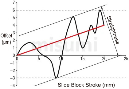
■ Straightness
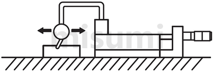
The maximum deviation of the slide table from the ideal movement axis (the straight line connecting the start and end points, shown as the red line in the diagram below; the black line represents the actual movement path) during full-stroke movement. Measurement method: Place a dial indicator on the slide table with the pointer touching the reference block. Move the slide table through its full stroke and measure the maximum displacement, which is the straightness.
Product Overview
The MISUMI E-XYZSG series linear ball guide type stage is an economical stage. It can be used as a simple position adjustment stage. The main body is made of stainless steel, providing a certain degree of rust resistance. The guide mechanism uses a linear ball guide, which provides the necessary level of accuracy. Due to localized production in China and improved manufacturing processes, the price has been significantly reduced.
Dimensional Drawing

Material Table
| Type |  Material Material |  Surface treatment Surface treatment |
| Body | SUS440C | Electroless nickel plating |
| Z bracket | Aluminum alloy | Natural anodized |
Alterations
■ Alterations
| Alterations | Change the position of the micrometer knob | |||
| Spec. | Center | Side facing up | Side facing down | Reverse |
| Code | A | C | CU | R |
Specification Table
| Type | Stage surface (mm) | Travel distance (mm) X, Y, Z axes | Load capacity (N) | Straightness (µm) | Minimum reading (µm) | Weight (kg) | |
 Type Type |  No. No. | ||||||
| E-XYZSG | 40 | 40 × 40 | ±6.5 | 49 | Within 10 | 10 | 0.78 |
| 50 | 50 × 50 | 1.08 | |||||
| 60 | 60 × 60 | 1.38 | |||||
| 70 | 70 × 70 | 2 | |||||
| 80 | 80 × 80 | ±12.5 | 3 | ||||
■ Travel distance
The catalog drawing dimensions are based on a stroke of 0 mm. Using this as a reference, the distance moved in the left and right directions is the travel distance.
■ Load capacity
Refers to the force that the slide table can withstand when the workpiece's center of gravity is located at the center of the slide table, measured in N. If used beyond the load capacity, the slide table may not operate smoothly or may become stuck. When installing the linear motion slide table vertically or upside down, the accuracy may be less than the values indicated in the product catalog. Please take note.
■ Straightness
The maximum deviation of the slide table from the ideal movement axis (the straight line connecting the start and end points, shown as the red line in the diagram below; the black line represents the actual movement path) during full-stroke movement. Measurement method: Place a dial indicator on the slide table with the pointer touching the reference block. Move the slide table through its full stroke and measure the maximum displacement, which is the straightness.
Product Features
Feature 1: Shortened production lead time, with delivery in as fast as 5 days.
Feature 2: Achieves a low price by simplifying the structure and improving the manufacturing process.
Feature 3: Supports various additional machining options to meet installation requirements in different situations.
Feature 4: Improved clamping mechanism provides greater holding force for the slide table compared to the standard clamping mechanism.
Feature 2: Achieves a low price by simplifying the structure and improving the manufacturing process.
Feature 3: Supports various additional machining options to meet installation requirements in different situations.
Feature 4: Improved clamping mechanism provides greater holding force for the slide table compared to the standard clamping mechanism.
Usage Method
■ Installation method for X-axis slide table
When installing the slide table onto the base, the installation is generally performed by moving the slide table surface. Please refer to the diagram below.
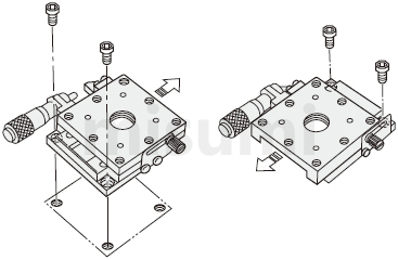
 The above diagram is for installation example demonstration only. For detailed shapes and specifications of the slide table, please refer to the respective product catalog or 3D data.
■ Installation orientation
Horizontal, inverted, side horizontal, or side vertical installation can be selected. For other installation methods, please pay special attention.
Depending on the installation orientation, load capacity and accuracy may vary significantly.
○: Same load capacity as horizontal installation.
△: Approximately one-third of the horizontal load capacity is the general standard. If the product catalog lists the vertical load capacity, please give priority to the catalog.
■Vertical Use of X-Axis Stage
When using the X-axis stage vertically, please pay attention to the feed direction and avoid aligning it with the direction of gravity.
When using a micrometer knob type stage, please note that the stage is reset by a tension spring. If the applied force exceeds the spring load, the stage platform may drop. In such cases, additional processing can be selected as a solution.
Please avoid applying loads in the vertical direction that exceed the load capacity.
When installing the slide table onto the base, the installation is generally performed by moving the slide table surface. Please refer to the diagram below.
 The above diagram is for installation example demonstration only. For detailed shapes and specifications of the slide table, please refer to the respective product catalog or 3D data.
■ Installation orientation
| Diagram |  |  |  |  |
| Installation orientation | Horizontal | Inverted | Side-mounted horizontal | Side-mounted vertical |
| Load resistance characteristics | ○ | ○ | △ | △ |
Horizontal, inverted, side horizontal, or side vertical installation can be selected. For other installation methods, please pay special attention.Depending on the installation orientation, load capacity and accuracy may vary significantly.○: Same load capacity as horizontal installation.△: Approximately one-third of the horizontal load capacity is the general standard. If the product catalog lists the vertical load capacity, please give priority to the catalog.■Vertical Use of X-Axis Stage
When using the X-axis stage vertically, please pay attention to the feed direction and avoid aligning it with the direction of gravity.
When using a micrometer knob type stage, please note that the stage is reset by a tension spring. If the applied force exceeds the spring load, the stage platform may drop. In such cases, additional processing can be selected as a solution.
| Incorrect usage | Correct usage |
| (Generally) If the applied force exceeds the tension load of the spring, the stage platform may fall due to insufficient load capacity. | After selecting the additional machining to change the micrometer knob position, the stage surface will not drop even when used vertically. |
 |  |
Please avoid applying loads in the vertical direction that exceed the load capacity.Precautions
■ Operating temperature and environment
Recommended operating environment: 10–50°C, 20–70% RH (no condensation)
Accuracy-guaranteed environment: 22±5°C, 20–70% RH (no condensation)
■ Guide mechanism
This stage uses a linear ball guide as the guiding mechanism.
■ Clamping mechanism
(1) The clamping mechanism of the stage is fixed by the friction force generated by tightening the screws. Therefore, if an external force exceeding the friction force of the clamping mechanism is applied, the stage will move. Please take appropriate measures during use to prevent the stage surface from moving. If additional clamping reinforcement is required, you can choose either disc clamping or opposed clamping.
(2) Holding force refers to the amount of force that keeps the stage surface from moving when clamped. Since the maximum holding force varies with changes in tightening torque, please ensure a sufficiently large safety factor in your design.
■ Feed Mechanism
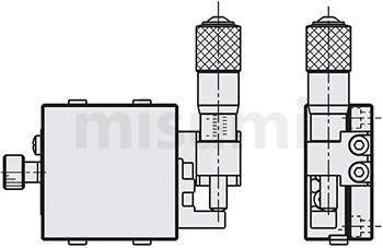
A stage equipped with a micrometer knob, as shown in the figure below, is generally referred to as the standard type. The installation space, installation orientation, and operation method can be freely selected. However, due to the structure of the product, there are some models where the installation position of the micrometer knob cannot be changed. For details, please refer to the [Additional Machining] section at the bottom of each product page.
■ Flatness of the mounting surface
The upper and lower slide table surfaces may become deformed due to differences in the flatness of the mounting surface. Deformation of the slide table surface may result in gaps, inability to achieve the specified preload causing looseness, or excessive preload leading to poor sliding performance. Therefore, it is recommended to maintain the flatness of the mounting surface at around 5 micrometers.
Recommended operating environment: 10–50°C, 20–70% RH (no condensation)
Accuracy-guaranteed environment: 22±5°C, 20–70% RH (no condensation)
■ Guide mechanism
This stage uses a linear ball guide as the guiding mechanism.
■ Clamping mechanism
(1) The clamping mechanism of the stage is fixed by the friction force generated by tightening the screws. Therefore, if an external force exceeding the friction force of the clamping mechanism is applied, the stage will move. Please take appropriate measures during use to prevent the stage surface from moving. If additional clamping reinforcement is required, you can choose either disc clamping or opposed clamping.
(2) Holding force refers to the amount of force that keeps the stage surface from moving when clamped. Since the maximum holding force varies with changes in tightening torque, please ensure a sufficiently large safety factor in your design.
■ Feed Mechanism
A stage equipped with a micrometer knob, as shown in the figure below, is generally referred to as the standard type. The installation space, installation orientation, and operation method can be freely selected. However, due to the structure of the product, there are some models where the installation position of the micrometer knob cannot be changed. For details, please refer to the [Additional Machining] section at the bottom of each product page.
■ Flatness of the mounting surface
The upper and lower slide table surfaces may become deformed due to differences in the flatness of the mounting surface. Deformation of the slide table surface may result in gaps, inability to achieve the specified preload causing looseness, or excessive preload leading to poor sliding performance. Therefore, it is recommended to maintain the flatness of the mounting surface at around 5 micrometers.
Example of Use
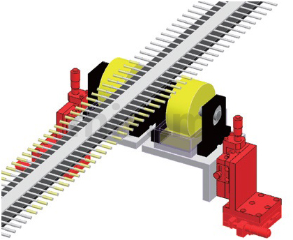
Mechanism name: Cotton swab glue application position adjustment
Application Industries
| Electronics/Home Appliances | Automotive | Medical | ||
 |  |  | ||
| Smartphones | Semiconductors | Lithium batteries | ||
 |  |  |
Related Products
| Economical Electric Slide Table X-Axis | Economical Electric Slide Table XY-Axis | Economical Electric Slide Table Z-Axis | ||
 |  |  | ||
| Representative model: C-XMBS420-L-A-2 | Representative model: C-XYMBS420-L-A-2 | Representative model: C-ZMBS420-L-A-2 | ||
| Advantage: Low cost, fast delivery | Advantage: Low cost, fast delivery | Advantage: Low cost, fast delivery |