X-Axis Motorized Positioning Stages, Linear Ball Guide Type, Positioning Repeatability ±5μ
Brand :
MISUMI
Caution
Product Description
Product Overview
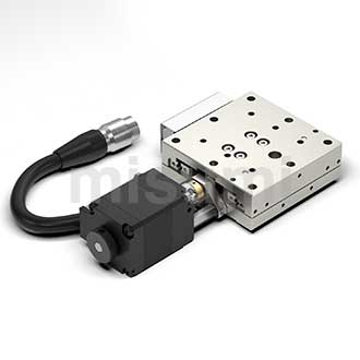
The MISUMI C-XMBS series electric positioning stage is an economical positioning stage equipped with a two-phase stepper motor. Can be used as a positioning stage for position adjustment in automation equipment. The main body is made of 20Cr steel with chemical nickel plating, providing not only high rigidity but also excellent rust resistance. An integrated linear ball guide is used for guidance, ensuring the required precision. By simplifying the structure and improving the manufacturing process, the price has been significantly reduced.
Dimensional Drawing

 The length of the motor-side connector cable varies depending on the model. Please refer to the actual product.The purchased model already includes the positioning stage body and the corresponding driver and cable, so there is no need to purchase them separately.The above image shows the situation when selecting cover plate L. Please confirm the detailed dimensions when selecting the cover plate R using CAD data.
Stepper Motor Mounting Bracket
C-XMBS□□□-R-S3
 The above image shows the situation when the cover plate R is selected. Please confirm the detailed dimensions when selecting cover plate L using the CAD data.
 Material Material |  Surface Treatment Surface Treatment |  Accessories Accessories |
| Alloy Steel | Electroless Nickel Plating | Positioning Pins Quantity: 4 pcs |
Specification Overview
 Material Material |  Surface Treatment Surface Treatment | Movement (mm) | Load Capacity (N) | Single-Axis Accuracy Specification (μm) | |
| One-Way Positioning Accuracy | Repetitive Positioning Accuracy | ||||
| Equivalent to SUS440C | Electroless Nickel Plating | 18~43 | 98~117.6 | Within 20 | ±Within 5.0 |
 Accessory: Locating pin Quantity: 4 pcs
■Travel Distance
Indicates the distance the sliding table can move. (In each product page, illustrations are provided at the center position of the stroke.)
■Load Capacity
The maximum load that can be applied to the center of the positioning stage, and the value that can be driven at maximum speed.
■Unidirectional Positioning Accuracy
Positioning is performed sequentially at fixed intervals in one direction from the reference point (end of stroke). The actual measured values (the actual moved position from the reference point) and the theoretical values (the commanded position to be moved) at each positioning point throughout the entire stroke are measured and calculated. The maximum difference between these values is defined as the unidirectional positioning accuracy.

■Repeat Positioning Accuracy
Repeat positioning from the same direction at any point 7 times, measure the deviation of the stop position, and calculate half of the maximum difference of this deviation. Repeat this operation at three points: the middle and both ends of the stroke. The maximum calculated value is defined as the repeatability accuracy.

Specification Table
Position| Type | Slide Table Length (mm) |  Cover Plate |  Motor Motor |  Driver |  Cable Length (m) | Mechanical Specifications | Accuracy Specifications | Sensor | ||||||||||||
 Type Type |  Type Type | Travel distance (mm) | Load capacity (N) | Weight (kg) | Resolution (pulses) | Maximum speed | Unidirectional positioning accuracy | Repeat positioning accuracy | Non-effective movement | Parallelism | Motion straightness | Motion parallelism | Limit sensor | Origin sensor (ORG1) | ||||||
| C-XMBS | X axis | 420 | 40 × 40 | L | Blank (with standard stepper motor) S3 (with 28-frame stepper motor mounting bracket) | A (Single-axis pulse driver) N (No driver) E (EtherCat bus driver) | 2 4 | 18 | 98 | 0.4 | 5 µm | 10 mm/sec | Within 20 µm | Within ±5.0 µm | 10µm | 30 µm | 10µm | 20µm | Yes | Yes |
| R | ||||||||||||||||||||
| 630 | 60 × 60 | L | 28 | 0.6 | ||||||||||||||||
| R | ||||||||||||||||||||
| 650 | 60 × 100 | L | 43 | 0.8 | ||||||||||||||||
| R | ||||||||||||||||||||
| 820 | 80 × 80 | L | 20 | 117.6 | 1.1 | |||||||||||||||
| R | ||||||||||||||||||||
Driver: The pulse driver model used in this series is E-DR42B.Bus driver brand and model: Leadshine DM3C-EC522.Cable: The cable models used in this series are HRS12-2M (2-meter cable) / HRS12-4M (4-meter cable).Servo motor mounting bracket type. Recommended motor brands: Yaskawa, Inovance, Mitsubishi, Leadshine, Moons, etc. Recommended power: 50W, 100W. Please carefully check the motor mounting dimensions.■ General specifications
| Feed Screw | Ball Screw ⌀6, Lead 1 mm | |
| Guide Rail | Linear Ball Guide Type | |
| Motor | Shape | 2-Phase Stepping Motor |
| Step Angle | 1.8° | |
| Driver | Power Voltage | DC12 to 50 V |
| Output Current | 0.1 to 2.2 A | |
| Pulse Signal Voltage | 5 to 24 V | |
| Pulse Input Method | Dual Pulse / Pulse + Direction | |
| Number of Subdivisions | 200 to 51200 | |
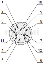
| Connector | Part Number | HR10A-10J-12P (Hirose) |
| Receiving side part number | HR10A-10P-12S (Hirose) | |
| Sensor Substrate | Power Voltage | DC24±10% |
| Sensor Type | Miniature Photoelectric Sensor EE-SX4320 (Omron) | |
| Control Output | NPN Open Collector Output | |
| Output Logic | During detection (shading): Output transistor OFF (non-conducting) | |
■ Connector Pin Arrangement
■ Wiring Diagram
■ Wiring Diagram


t1<0.1us t2 ≥ 0.9us t3 ≥ 10us
t4: ENA (Enable Signal) t4 should be set high at least 10µs before DIR. In general, it is recommended to leave ENA+ and ENA- unconnected.
Product Features
Feature 1: By simplifying the structure and improving the manufacturing process, a lower price is achieved.
Feature 2: By rearranging the internal steel balls and extending the base, selectable strokes from 18 mm to 43 mm are achieved.
Feature 3: By adding positioning holes to the upper and lower bases of the positioning stage, quick assembly and disassembly are achieved.
Feature 4: 40/60/80 series positioning hole diameters and positions are standardized, allowing positioning stages of different sizes to be combined interchangeably for diverse assembly options.
Feature 5: The voltage for limit sensors/actuators has been increased to 32 V, reducing failures such as burnout caused by unstable voltage.
Feature 2: By rearranging the internal steel balls and extending the base, selectable strokes from 18 mm to 43 mm are achieved.
Feature 3: By adding positioning holes to the upper and lower bases of the positioning stage, quick assembly and disassembly are achieved.
Feature 4: 40/60/80 series positioning hole diameters and positions are standardized, allowing positioning stages of different sizes to be combined interchangeably for diverse assembly options.
Feature 5: The voltage for limit sensors/actuators has been increased to 32 V, reducing failures such as burnout caused by unstable voltage.
Usage Method
The C-XMBS series positioning stage is equipped with a two-phase stepper motor, MISUMI two-phase stepper motor driver, and cables. Customers only need to prepare a 24 V power supply and a host controller (PLC or motion control card) to use it. The connection example between each product is shown in the figure below.

* 1 The cable in the dotted box is 2m cable
Precautions
■ Positioning Stage Operating Environment
Operating Environment: 10 to 50°C, 20 to 70%RH (non-condensing)
Recommended operating environment: 22±5°C, 20 to 70%RH (non-condensing)
Please avoid using the positioning stage products in the following environments
(1) Dusty environments (especially metal powder)
(2) Environments with direct sunlight or heat radiation
(3) Near fire sources
(4) Environments with corrosive or flammable gases
(5) Environments with splashing water or oil
(6) Environments with strong vibration or impact
(7) Environments with organic solvents or high salt content
■About Positioning Stage Maintenance
There is no unified regular maintenance standard due to differences in grease types and usage environments. Depending on the drive conditions and the type of guide rail, please be sure to check the grease at least once a month.
■ About Wiring
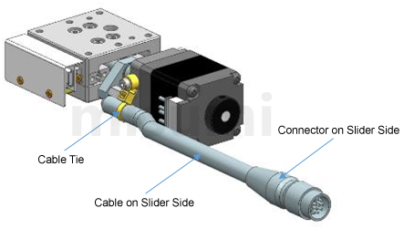
The motor and sensor cables of this product use a cable + connector method. If the cable on the side of the positioning stage is frequently bent, it can easily cause the cable tie to break, which may lead to loose motor terminals and sensor terminals, resulting in poor contact or wire breakage. It is recommended to secure the slider side connector during wiring.
Operating Environment: 10 to 50°C, 20 to 70%RH (non-condensing)
Recommended operating environment: 22±5°C, 20 to 70%RH (non-condensing)
Please avoid using the positioning stage products in the following environments
(1) Dusty environments (especially metal powder)
(2) Environments with direct sunlight or heat radiation
(3) Near fire sources
(4) Environments with corrosive or flammable gases
(5) Environments with splashing water or oil
(6) Environments with strong vibration or impact
(7) Environments with organic solvents or high salt content
■About Positioning Stage Maintenance
There is no unified regular maintenance standard due to differences in grease types and usage environments. Depending on the drive conditions and the type of guide rail, please be sure to check the grease at least once a month.
■ About Wiring
The motor and sensor cables of this product use a cable + connector method. If the cable on the side of the positioning stage is frequently bent, it can easily cause the cable tie to break, which may lead to loose motor terminals and sensor terminals, resulting in poor contact or wire breakage. It is recommended to secure the slider side connector during wiring.
 Image for reference only
 Application Industries
| Electronics/home appliance | Automotive | Medical | ||
 |  |  | ||
| Smart phone | Semiconductor | Lithium battery | ||
 |  |  |
Related Products
| Stepper Driver | High-Precision X-Axis Automatic Positioning Stage | Medium Precision X-Axis Automatic Stage | ||
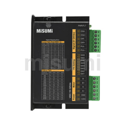 | 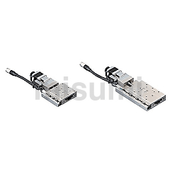 | 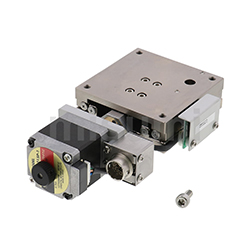 | ||
| Representative Model: C-DR42A | Representative Model: XMSG413-LA24-C-N | Representative Model: XMBS415-L-N |
Related Documents
■ Driver
Compatible drivers support dual-pulse and pulse + direction control. For installation dimensions and user manual, please refer to: E-DR42B.
■ Bus Driver
For installation dimensions and user manual of the driver, refer to Leadshine DM3C-EC522
■ Positioning Pin Drawing

*Starting from June 1, 2023, the equipped drivers support two types of pulse input: dual pulse and pulse + direction.
Economy Automatic Slide Table Series List
If you require other multi-axis combinations, please contact ts@misumi.com.vn.
| Direction of movement | ||||||
| X axis | Rotary axis | Goniometer | Z axis | Multi-axis combination | ||
| Guide mechanism | 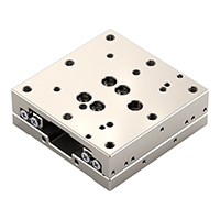 Linear ball | Thin type, repeatability ±1.5µ Standard type, repeatability ±1µ Standard type, repeatability ±1.5µ With recirculator, standard type, repeatability ±1.5µ/±2µ With recirculator, standard type, repeatability ±1µ With recirculator cover, standard type, repeatability ±1µ Repeatability ±5µ | — | — | Lifting type Repeatability ±5µ Repeatability ±5µ | Repeatability ±5µ |
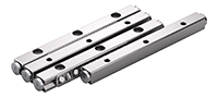 Crossed roller | Repeatability ±1.5µ Repeatability ±1µ | — | Repeatability ±0.006° Repeatability ±0.01° | Repeatability ±1µ | Repeatability ±0.01° | |
| Displacement mechanism | 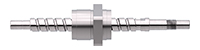 Ball screw | — | Repeat positioning accuracy ±0.005° Repeat positioning accuracy ±0.01° | — | — | — |
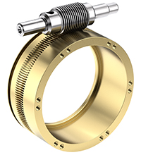 Worm gear and worm | — | Repeatability ±0.05° Repeatability ±0.08° | — | — | — | |