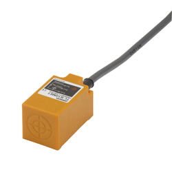
Rectangular standard type proximity sensor TL-N/Q
Caution
Product Description
Supports a wide range of models for various uses.
[Features]
· Easy installation, suitable for high-speed pulse generators, high-speed rotating control, etc.
·Direct metal installation possible (Type -N)
· With a wide variety of models, ideal for various limit control, counting control, etc. (Type -N)
Drawing
Main body

Product Specification
Rating / Performance
DC 2-wire connection
| Items | Type | ||||
|---|---|---|---|---|---|
| TL-Q5MD* | TL-N7MD* | TL-N12MD* | TL-N20MD* | ||
| Sensing Distance | 5 mm +/- 10% | 7 mm +/- 10% | 12 mm +/- 10% | 20 mm +/- 10% | |
| Set distance | 0 to 4 mm | 0 to 5.6 mm | 0 to 9.6 mm | 0 to 16 mm | |
| Hysteresis | 10% or less of detection distance | ||||
| Detectable objects | Magnetic metals (For non-magnetic metals, the detection distance will be reduced. See "Characteristic Data" | ||||
| Standard detected object | 18 x 18 x 1 mm, steel | Steel sheet 30 x 30 x 1 mm | 40 x 40 x 1 mm, steel | 50 x 50 x 1 mm, steel | |
| Response frequency * | 500 Hz | 300 Hz | |||
| Power Supply Voltage (Operating Voltage Range) | 12 to 24 V DC, ripple (p-p) 10% or less (DC10 to 30 V) | ||||
| Leakage current | 0.8 mA or less | ||||
| Control output | Contact Capacity | 3 to 100 mA | |||
| Residual voltage | 3.3 V or less (when load current is 100 mA, cord length is 2 m) | ||||
| Indicator light | D1 type: operation display (red), setting display (green) D2 type: operation display (red) | ||||
| Operating mode (When a detected object approaches) | D1 type: NO D2 type: NC For details, refer to the time chart in the "Input/Output Stage Circuit Diagram" | ||||
| Protection circuit | Load Short Circuit Protection, Surge Absorption | ||||
| Ambient temperature range | When operating, when storing: -25 to +70°C each (no freezing or condensation) | ||||
| Ambient humidity range | Operating, Storage: 35 to 95%RH each (no condensation) | ||||
| Effect of temperature | Within +/-10% of detection distance at +23°C within the temperature range of -25 to +70°C | ||||
| Effect of voltage | Within +/-15% of the rated power supply voltage, within +/-2.5% of the sensing distance at the rated power supply voltage | ||||
| Insulation resistance | 50 MΩ or more (500 V DC insulation resistance tester) between all live parts and the case | ||||
| Withstand voltage | 1,000 V AC for 1 minute between all live parts and the case | ||||
| Vibration (endurance) | 10 to 55 Hz, 1.5 mm double amplitude, 2 hr in each direction of X, Y, and Z | ||||
| Shock (endurance) | 500 m/s2 in Each X, Y, Z Direction 3 times | 1,000 m/s2 in Each X, Y, Z Direction 10 times | |||
| Protective Structure | IEC standard IP67, OMRON internal standard: Oil resistance | ||||
| Connection method | Pre-wired type (standard cord length 2 m) | ||||
| Weight (packed state) | Approx. 85 g | Approximately 165 g | Approx. 235 g | Approx. 330 g | |
| Material | Case | Heat-resistant ABS | |||
| Detecting surface | |||||
| Accessory | Instruction manual | Installation metal fitting, installation screw (M4 x 25), instruction manual | Installation metal fitting, installation screw (M4 x 30), instruction manual | Installation metal fitting, installation screw (M5 x 40), instruction manual | |
*The response frequency is an average value. The measurement conditions are to use the standard detected object, set the interval between the detected objects to twice that of the standard detected object, and set the distance to 1/2 of the sensing distance.
Direct current 3-Wire Type
| Items | Type | ||
|---|---|---|---|
| Model TL-Q2MC1 | Model TL-Q5MC* / Model TL-Q5MB1 | ||
| Sensing Distance | 2 mm +/- 15% | 5 mm +/- 10% | |
| Set distance | 0 to 1.5 mm | 0 to 4 mm | |
| Hysteresis | 10% or less of detection distance | ||
| Detectable objects | Magnetic metals (For non-magnetic metals, the detection distance will be reduced. See "Characteristic Data" | ||
| Standard detected object | Steel 8 x 8 x 1 mm | Steel sheet 15 x 15 x 1 mm | |
| Response time | - | 2 ms or less | |
| Response frequency * | 500 Hz | ||
| Power Supply Voltage (Operating Voltage Range) | 12 to 24 V DC, ripple (p-p) 10% or less (DC10 to 30 V) | ||
| Current Consumption | 15 mA or less (at 24 V DC, at no load) | 10 mA or less (at 24 V DC) | |
| Control output | Contact Capacity | NPN open collector 100 mA or less (30 V DC or less) | Model TL-Q5MC*: NPN open collector, 50 mA or less (30 V DC or less) Model TL-Q5MB*: PNP open collector, 50 mA or less (30 V DC or less) |
| Residual voltage | 1 V or less (when load current is 100 mA and cord length is 2 m) | 1 V or less (when load current is 50 mA and cord length is 2 m) | |
| Indicator light | Detection display (red) | ||
| Operating mode (When a detected object approaches) | NO | B1/C1 type: NO C2 type: NC | |
| For details, refer to the time chart in the "Input/Output Stage Circuit Diagram" | |||
| Protection circuit | Reverse Connection Protection, Surge Absorption | ||
| Ambient temperature range | During operation and storage: -10 to +60°C each (no freezing or condensation) | Operating: -25 to +70°C, Storage: -25 to +70°C (no freezing or condensation) | |
| Ambient humidity range | Operating, Storage: 35 to 95%RH each (no condensation) | ||
| Effect of temperature | +/-10% or less of detection distance at +23°C within the temperature range of -10 to +60°C | +/-20% or less of detection distance at +23°C within the temperature range of -25 to +70°C | |
| Effect of voltage | Within +/-10% of the rated power supply voltage, within +/-2.5% of the sensing distance at the rated power supply voltage | ||
| Insulation resistance | 50 MΩ or more (500 V DC insulation resistance tester) between all live parts and the case | 5 MΩ or more (500 V DC insulation resistance tester) between all live parts and the case | |
| Withstand voltage | 1,000 V AC for 1 minute between all live parts and the case | 500 V AC 50/60 Hz 1 min between batch of live parts and the case | |
| Vibration (endurance) | 10 to 55 Hz, 1.5 mm double amplitude, 2 hr in each direction of X, Y, and Z | ||
| Shock (endurance) | 1,000 m/s2 in Each X, Y, Z Direction 10 times | 200 m/s2 in Each X, Y, Z Direction 10 times | |
| Protective Structure | IEC standard IP67, OMRON internal standard: Oil resistance | IEC standard IP67 | |
| Connection method | Pre-wired type (standard cord length 2 m) | ||
| Weight (packed state) | Approx. 60 g | Approx. 90 g | |
| Material | Case | Heat-resistant ABS | |
| Detecting surface | |||
| Accessory | Instruction manual | - | |
*The response frequency is an average value. The measurement conditions are to use the standard detected object, set the interval between the detected objects to twice that of the standard detected object, and set the distance to 1/2 of the detection distance.
Direct current 3-Wire/Alternating current 2-Wire
| Items | Type | |||
|---|---|---|---|---|
| Model TL-N5ME*, Model TL-N5MY* | Model TL-N10ME*, Model TL-N10MY*, Model TL-N10MF1 | Model TL-N20ME*, Model TL-N20MY* | ||
| Sensing Distance | 5 mm +/- 10% | 10 mm +/- 10% | 20 mm +/- 10% | |
| Set distance | 0 to 4 mm | 0 to 8 mm | 0 to 16 mm | |
| Hysteresis | 15% or less of detection distance | |||
| Detectable objects | Magnetic metal (Detection distance is reduced for non-magnetic metals. See "Characteristic Data" | |||
| Standard detected object | Steel sheet 30 x 30 x 1 mm | 40 x 40 x 1 mm, steel | 50 x 50 x 1 mm, steel | |
| Response frequency *1 | E/F type: 500 Hz Y type: 10 Hz | E type: 40 Hz Y type: 10 Hz | ||
| Power supply voltage *2 (Operating Voltage Range) | E/F type: 12 to 24 V DC, ripple (p-p) 10% or less (DC10 to 30 V) Y type: 100 to 220 V AC (90 to 250 V AC) 50/60 Hz | |||
| Current Consumption | E/F type: 8 mA or less (at 12 V DC), 15 mA or less (at 24 V DC) | |||
| Leakage current | Y type: See "Performance Data" | |||
| Control output | Contact Capacity | E/F type: 100 mA or less (at 12 V DC), 200 mA or less (at 24 V DC) Y type: 10 – 200 mA | ||
| Residual voltage | E/F type: 1 V or less (at 200 mA) Y type: See "Performance Data" | |||
| Indicator light | E/F type: detection indicator (red) Y type: operation indicator (red) | |||
| Operating mode (When a detected object approaches) | E1/F1/Y1 type: NO E2/Y2 type: NC For details, refer to the time chart in the "Input/Output Stage Circuit Diagram" | |||
| Protection circuit | E type: Reverse connection protection, surge absorb Y type: Surge absorb | |||
| Ambient temperature range | When operating, when storing: -25 to +70°C each (no freezing or condensation) | |||
| Ambient humidity range | Operating, Storage: 35 to 95%RH each (no condensation) | |||
| Effect of temperature | Within +/-10% of detection distance at +23°C within the temperature range of -25 to +70°C | |||
| Effect of voltage | E/F type: Within +/-10% of the rated supply voltage, the detection distance varies by +/-2.5% or less at the rated supply voltage. Y type: Within +/-10% of the rated supply voltage, the detection distance varies by +/-1% or less at the rated supply voltage. | |||
| Insulation resistance | 50 MΩ or more (500 V DC insulation resistance tester) between all live parts and the case | |||
| Withstand voltage | E/F type: AC 1,000 V 50/60 Hz 1 min between all live parts and the case Y type: AC 2,000 V 50/60 Hz 1 min between all live parts and the case | |||
| Vibration (endurance) | 10 to 55 Hz, 1.5 mm double amplitude, 2 hr in each direction of X, Y, and Z | |||
| Shock (endurance) | 500 m/s2 in Each X, Y, Z Direction 10 times | |||
| Protective Structure | IEC standard IP67, OMRON internal standard: Oil resistance | |||
| Connection method | Pre-wired type (standard cord length 2 m) | |||
| Weight (packed state) | Approx. 190 g | Approx. 240 g | Approx. 340 g | |
| Material | Case | Heat-resistant ABS | ||
| Detecting surface | ||||
| Accessory | E type: installation metal fitting, installation screw (+) (M4 x 25), instruction manual Y type: instruction manual | E/F type: installation metal fitting, installation screw (+) (M4 x 30), instruction manual Y type: instruction manual | E Type: installation metal fitting, installation screw (+) (M5 x 40), instruction manual Y type: instruction manual | |
*1. The response frequency is an average value. The measurement conditions are to use the standard detected object, set the interval between the detected objects to twice that of the standard detected object, and set the distance to 1/2 of the detection distance.
*2. The E type (direct current switching type) can be used with a fully rectified power supply of 24 V DC +/-10% (average value).