Amplifier Relay Proximity Sensor E2EC
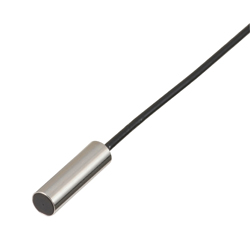
Brand :
OMRON
Caution
- There were errors in some product specifications. Apologies for any inconvenience this may cause.
Corrections were made on June 5, 2019.
Product Description
Achieves long-distance detection in an ultra compact size.
[Features]
· Compact shielded type sensor head, ⌀3 to M12
· Can be recessed in metal
· Robot cord standard (2-wire direct current type)
· Indicator lamp on relay cord (amplifier section) for easy operation check
· Power supply voltage range: 5 to 24 V DC (3-wire direct current type only)
Drawing
Main body

Product Specification
Rating / Performance
| Items | Type | ||||||
|---|---|---|---|---|---|---|---|
| Model E2EC-CR8D* | Model E2EC-C1R5D* | Model E2EC-C3D* | Model E2EC-X4D* | Model E2EC-CR5C1 | Model E2EC-C2R5C1 | ||
| Type | DC 2-wire connection | Direct current 3-Wire Type | |||||
| Sensing Distance | 0.8 mm +/- 15% | 1.5 mm +/- 10% | 3 mm +/- 10% | 4 mm +/- 10% | 0.5 mm +/- 15% | 2.5 mm +/- 10% | |
| Set distance | 0 to 0.56 mm | 0 to 1.05 mm | 0 to 2.1 mm | 0 to 2.8 mm | 0 to 0.3 mm | 0 to 1.7 mm | |
| Hysteresis | 10% or less of detection distance | ||||||
| Detectable objects | Magnetic metals (For non-magnetic metals, the detection distance will be reduced. See "Characteristic Data" | ||||||
| Standard detected object | Steel 5 x 5 x 1 mm | Steel 8 x 8 x 1 mm | Steel sheet 12 x 12 x t1 mm | Steel 5 x 5 x 1 mm | Steel 8 x 8 x 1 mm | ||
| Response frequency *1 | 1.5 kHz | 1 kHz | |||||
| Power Supply Voltage (Operating Voltage Range) | 12 to 24 V DC, ripple (p-p) 10% or less (DC10 to 30 V) | 5 to 24 V DC, ripple (p-p) 10% or less (DC4.75 to 30 V) | |||||
| Current Consumption | - | 10 mA or less | |||||
| Leakage current | 0.8 mA or less | - | |||||
| Control output | Contact Capacity | 5 to 100 mA | NPN open collector output 100 mA or less (30 V DC or Less) | ||||
| Residual voltage | 3 V or less (when load current is 100 mA, cord length is 2 m) | 1 V or less (when load current is 100 mA, cord length is 2 m) | |||||
| Indicator light | D1 type: operation display (red), setting display (green) D2 type: operation display (red) | Detection display (red) | |||||
| Operating mode (When a detected object approaches) | D1 type: NO D2 type: NC For details, refer to the time chart in the "input/output stage circuit diagram" | NO For detail, see the "input/output stage circuit diagram" timing chart | |||||
| Protection circuit | Load Short Circuit Protection, Surge Absorption | Surge Absorption | |||||
| Ambient temperature range | When operating, when storing: -25 to +70°C each (no freezing or condensation) *2 | ||||||
| Ambient humidity range | Operating, Storage: 35 to 95%RH each (no condensation) | ||||||
| Effect of temperature | +/-20% or less of detection distance at +23°C within the temperature range of -25 to +70°C | ||||||
| Effect of voltage | Within +/-15% of the rated power supply voltage Within +/-2.5% of the detection distance at the rated power supply voltage | Within the operating voltage range of 4.75 to 30 V Within +/-5% of the detection distance at the rated power supply voltage | |||||
| Insulation resistance | 50 MΩ or more (500 V DC insulation resistance tester) between all live parts and the case | ||||||
| Withstand voltage | 1,000 V AC for 1 minute between all live parts and the case | 500 V AC for 1 minute between all live parts and the case | |||||
| Vibration (endurance) | 10 to 55 Hz, 1.5 mm double amplitude, 2 hr in each direction of X, Y, and Z | ||||||
| Shock (endurance) | 1,000 m/s2 in Each X, Y, Z Direction 10 times | 500 m/s2 in Each X, Y, Z Direction 10 times | |||||
| Protective Structure | IEC standard IP67, OMRON internal standard oil resistance (sensor head only) | IEC standard IP64 | |||||
| Connection method | Pre-wired type (standard cord length 2 m) | ||||||
| Weight (packed state) | Approx. 45 g | ||||||
| Material | Case | Brass | |||||
| Detecting surface | ABS | ||||||
| Tightening nut | - | Brass Nickel plating | - | ||||
| Toothed washer | - | Iron, zinc plating | - | ||||
| Accessory | Amplifier installation metal fitting, instruction manual | Instruction manual | |||||
*1. The response frequency is an average value. The measurement conditions are to use the standard detected object, set the interval between the detected objects to twice that of the standard detected object, and set the distance to 1/2 of the sensing distance.
*2. If there is a large temperature difference between the sensor section and the amplifier section, malfunction may occur, so please be careful.