(!)NOTE : Windows 7 users won’t be able to use some latest features of eCatalog/WOS since Microsoft is ending support for Windows 7 on 14 Jan, 2020. Please upgrade your system for uninterrupted services.
- Notice of End of Sales for Economy Series Pneumatic Equipment Category. More information.
Specification/Dimensions
-
M·N·O
- NB01
-
Allowable Voltage(V)
-
A· B· C
- CE01
-
Applicable pin/contact
- Male (plug)
- Female (socket)
-
Number Of Pins
-
Allowable Current(A)
-
Wire connection method
- Solder
- Crimp
-
Shell size
-
CAD
- 2D
Days to Ship
-
- All
- 6 Day(s) or Less
- 10 Day(s) or Less
- 14 Day(s) or Less
Specify Alterations
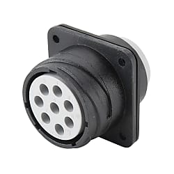
NB01/CE01 Waterproof Panel Mountable Receptacle (Bayonet Lock) (CE0102A-22-22-S-DRGC)


- Volume Discount
- UL
- JIS
- IP67
- Vibration-Resistant
- Solder
- Caulking
- Bayonet Lock
Copy Part Number URL to Clipboard
The part number URL has been copied into your clipboard.-
- Starting From :
- 2,127₹/Unit

-
- Order Qty :
-
-
- Total Price :
- ---
-
- Days to ship :
- ---
Select part number to Order Now/ Add to Cart

● Panel mount receptacles for connecting to straight and angled plugs.
● A connector that is used after mounting onto panels and then fixing in place. The O-ring used on the fitting surface prevents the intrusion of water drops, machining oil, dust, etc., from outside during fitting. Rear gasket (for front mount) made with chloroprene rubber is included.
● It has waterproof fitting structure class IP67, which makes it suitable for use in places exposed to water or oil.

· The crimp model (CE0102A) contact is sold separately.
· Panel mount receptacles cannot be fitted with one another.
· CE01 series are DDK products sold with Misumi model numbers.
Product Description
The CE01 series is consists of single-action lock connectors that allows for connection to a protection circuit compliant with JIS-B-6015, has waterproof and dust-proof structure, and is highly environment-resistant. Optimal for external connection of machine tools exposed to water droplets or cutting oil, factory automation related equipment, equipment used in adverse environments where there is a lot of dust, etc. #08, #12, and #16 contacts also have soldering type. Industrial equipment, machine tools, factory automation equipment, communication equipment, measuring instrument [Features] ●Bayonet lock method: An incorrect mating prevention structure with 5 positioning keys on the mating section. Insert the connector and rotate the coupling clockwise. A "click" sound allows you to confirm the secure mating. ● Waterproof (oil resistant) and dust-proof structure (IP67): The receptacle uses an O-ring to completely prevent the intrusion of water droplets, cutting oil, dust, etc., in the mating section when mated with the plug. In addition, by using a conduit with an O-ring on the connection side of the plug, waterproof requirements are met. ●Sequence structure with protection circuit: Each connector is equipped with 1 protective circuit ground contact that is electrically connected to the shell, and has a sequence structure that makes contact before other contacts when mating and disconnects last when disconnecting. ●Reduced labor-hours for connection (crimping type): Contacts are easy-to-wire crimping type, and can be pulled out to the rear using an extraction tool even if the circuit is changed or the wiring is incorrect. ●RoHS2 compliant product, JIS standard waterproofness
Specifications

| Wire Connection Type | Arrangement No. | Contact Shape | Gasket Type | Number of Cores | Shell Size | Contact Size |
| NB0102A Solder Connection CE0102A Crimp Connection | 18-1 | P Male (Pin) S Female (Socket) | DRGC (With Rear Gasket) | 10 | 18 | #16 |
| 18-11 | 5 | 18 | #12 | |||
| 20-15 | 7 | 20 | #12 | |||
| 20-29 | 17 | 20 | #16 | |||
| 22-14 | 19 | 22 | #16 | |||
| 22-22 | 4 | 22 | #8 | |||
| 22-23 | 8 | 22 | #12 | |||
| 24-10 | 7 | 24 | #8 | |||
| 24-28 | 24 | 24 | #16 | |||
| 28-21 | 37 | 28 | #16 | |||
| CE0102A Crimp Connection | 18-19A | 19 | 18 | #20 | ||
| 20-30A | 30 | 20 | #20 | |||
| 24-52A | 52 | 24 | #20 | |||
| 28-73A | 73 | 28 | #20 |
More Information

| Part Number |
|---|
| CE0102A-22-22-S-DRGC |
| Part Number | Price | Minimum Order Qty. | Volume Discount | Days to Ship | Connector series initials | A· B· C | M·N·O | Applicable pin/contact | Number Of Pins | Allowable Current (A) | Allowable Voltage (V) | Wire connection method | Shell size | Notice | Notice |
|---|---|---|---|---|---|---|---|---|---|---|---|---|---|---|---|
₹ 2,374.49 | 1 Piece(s) | 10 Day(s) or more | A・B・C | CE01 | - | Female (socket) | 4 | 46 | 500 ~ 700 | Crimp | 22 | 700V | 500V |
Loading...
Protection Circuit Connection Structural Diagram

About Compatible Products
NB01 connectors, CE01 connectors, and JL05 connectors are compatible with each other.Combination Method


Material / Finish
| Item | Materials | Finish |
|---|---|---|
| Shell (Body) | Aluminum Alloy | Black Chromate Treatment |
| Insulator | Polyester Resin | UL94V-0, Gray |
| Contact | Copper Alloy | Silver Plating |
| O-ring | Nitrile Rubber | Black |
| Coupling Nut | Aluminum Alloy | Black Chromate Treatment |
| Earth Lug | Steel Alloy | Silver Plating |
| Rear Gasket for Flange | Chloroprene Rubber | Black |
Electrical and Mechanical Properties, Compatible Wires
| Item | Characteristics | |||||||
|---|---|---|---|---|---|---|---|---|
| Rated Current | Contact Size | #20 | #16 | #12 | #8 | |||
| Maximum Value per 1 Piece | 5 A | 13 A | 23 A | 46 A | ||||
| Rated Voltage | Rating Classification | AC (r.m.s) | DC | |||||
| INST | 200 | 250 | ||||||
| A | 500 | 700 | ||||||
| D | 900 | 1,250 | ||||||
| Withstand Voltage | INST | 1,000 VAC (r.m.s) 1 minute | ||||||
| A | 2,000 VAC (r.m.s) 1 minute | |||||||
| D | 2,800 VAC (r.m.s) 1 minute | |||||||
| Insulation Resistance | 5,000 MΩ or more at 500 VDC | |||||||
| Contact Resistance | Contact Size | #20 | #16 | #12 | #8 | |||
| mΩ or less | 8 | 4 | 2 | 0.6 | ||||
| Operating Temperature Range | -55°C ~ +125°C | |||||||
| Waterproofing | IP67 Equivalent | |||||||
| Humidity | Relative Humidity 95% or less | |||||||
| Service Life | 500 Insertions and Removals | |||||||
| NB01 (Solder Type) Compatible Wires (Note 2) |
Contact Size | #16 | #12 | #8 | ||||
| Conductor Cross-sectional Area | 0.75 mm2 or less | 3.5 mm2 or less | 8 mm2 or less | |||||
| AWG Size | 18 or less | 12 or less | 8 or less | |||||
(Note 1) Rated voltage and voltage resistance are shown with rating classification symbols (INST, A; D). Refer as well to the table below.
Contact Arrangement Diagram
| Number of Contacts | 4 | 5 | 7 | 7 | 8 |
|---|---|---|---|---|---|
| Arrangement No. | 22-22 | 18-11 | 20-15 | 24-10 | 22-23 |
| Contact Size | #8 | #12 | #12 | #8 | #12 |
| Contact Arrangement (Note 1) (Note 2) |
 |
 |
 |
 |
 |
| Rating Classification | A | A | A | A | D (4), A (Others) |
| Number of Contacts | 10 | 17 | 19 | 19 | 24 |
|---|---|---|---|---|---|
| Arrangement No. | 18-1 | 20-29 | 18-19A | 22-14 | 24-28 |
| Contact Size | #16 | #16 | #20 | #16 | #16 |
| Contact Arrangement (Note 1) (Note 2) |
 |
 |
 |
 |
 |
| Rating Classification | A (3, 5, 6, 8), INST (Others) |
A | INST | A | INST |
| Number of Contacts | 30 | 37 | 52 | 73 |
| Arrangement No. | 20-30A | 28-21 | 24-52A | 28-73A |
| Contact Size | #20 | #16 | #20 | #20 |
| Contact Arrangement (Note 1) (Note 2) |
 |
 |
 |
 |
| Rating Classification | INST | A | INST | INST |
|---|
(Note 1) View from the male (pin) connector coupling surface.
(Note 2) The ○ in the arrangement table shows the earth terminals (for protection of terminal connections).
Panel Cut Size Drawing

| Compatible Shell Size |
φA ±0.5 |
φB +0.2 -0 |
C ±0.13 |
Mounting Screws (Reference) | Rear Mounting Panel Thickness Limit |
|
|---|---|---|---|---|---|---|
| Inch Screws | Metric Screws | |||||
| 18 | 30.2 | 3.3 | 26.97 | #4-40 | M3 | 3.0 or less |
| 20 | 34.9 | 3.3 | 29.36 | #4-40 | M3 | |
| 22 | 36.6 | 3.3 | 31.75 | #4-40 | M3 | |
| 24 | 39.7 | 4.3 | 34.92 | #6-32 | M4 | |
| 28 | 46.1 | 4.3 | 39.67 | #6-32 | M4 | |
Basic Information
| Connector Shape | Circular Type | Application | Cable-to-panel mount | Connection direction | Straight |
|---|---|---|---|---|---|
| Protection function (environmentally resistant) | Present | Representative Standard | UL | Other standards (JIS) | ○ |
| Removal method | Others |
- The specifications and dimensions of some parts may not be fully covered. For exact details, refer to manufacturer catalogs .
Payment Method
- Credit Card
-
- Debit Cart
-
- Net Banking
-
- UPI
-
- Cheque on delivery
-
- Online payment
-
Social Media
MISUMI India Contact
Copyright © MISUMI Corporation All Rights Reserved.


How can we improve?
How can we improve?
Thank you for your time.
Your feedback is essential for our continuous improvement
Privacy Policy
Thank you for your cooperation.
Thank you for your time.
Your feedback is essential for our continuous improvement
Please use the inquiry form.
Privacy Policy