Category 4 No-Blind-Zone Safety Light Curtain (Incident Angle > 2.5°)

Brand :
MISUMI
Caution
- As of Oct 2025, this product has SIL3 Class4 Certificate by ECM.
Certificate by TUV is under application phase.
Product Overview
This safety light curtain is a no-blind-zone light curtain designed in accordance with the IEC61508 SIL3 safety integrity level. Its internal MCU adopts a redundant design, and the dual-channel output features both periodic self-check and mutual check functions, providing comprehensive safety protection.
Comprehensive and complete self-check functions ensure that the light curtain is always in optimal working condition, effectively eliminating potential safety hazards.
Compatible with both optical synchronization and wired synchronization communication methods, featuring a compact size, elegant appearance, and outstanding performance to meet the needs of various application scenarios.
Supports multiple additional functions such as EDM and interlock reset to meet complex safety protection requirements.
The host computer configuration function allows users to flexibly configure the light curtain's functions and parameters according to on-site application needs, meeting personalized requirements. Multiple installation methods can adapt to various installation environments, making it convenient for users to install and maintain.
NOTICE:
This product is a safety light curtain certified to IEC 61508 (SIL 3).
The following certifications are currently under application:
ISO 13849-1 (PL e) for machinery safety (certification planned for February 2026)The following certifications are currently under application:
UL 61496-1/-2 (Type 4) for electro-sensitive protective equipment (certification planned for February 2026)
IEC 61496-1/-2 (Type 4) (certification planned for June 2026)
Therefore, when this product is used as a safety device, it is recommended to use it after obtaining the required certifications in accordance with the applicable safety standards, laws, or regulations of the country of use.
Product Features
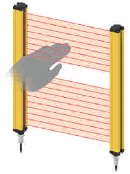
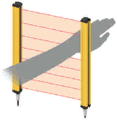
◆ No blind spots: Designed with blind spot-free technology for more comprehensive protection.
◆ Safety Level 4 Standard: Complies with IEC61508 SIL3 safety standard.
- IEC61508 SIL3
- UL Certificate
- CE Certificate
- TUV Certificate( application is under processing)
◆ High safety: Equipped with extensive self-check circuits, periodic dual self-checks and cross-checks to enhance safety.
◆ Multiple synchronization methods: Offers both optical and wired synchronization technologies for selection.
◆ Dual-channel redundant output: Designed with dual-circuit redundant output, each output channel features self-diagnostic pulses, enabling timely self-check and diagnosis of faults such as output channel overcurrent, short circuit with power supply, and mutual short circuit between outputs, ensuring safety and reliability.
◆ External EDM function: Enables dynamic monitoring of external devices (relays, contactors, etc.) connected to the light curtain output, preventing safety function failure caused by external device malfunctions.
◆ Interlock reset function: The light curtain offers an optional interlock reset function, supporting both manual and automatic reset modes.
◆ Host computer configuration function: The synchronization mode, EDM, and interlock reset functions can be flexibly configured via the host computer.
◆ Multiple installation methods: Suitable for various installation environments.
The factory default is set to optical synchronization mode (without EDM, automatic reset). Wired synchronization requires special software for modification; please refer to the manual for modification instructions.
| 8 Modes of Optical(Light) Synchronization/Wired Synchronization |
| NPN/PNP Output (No EDM, Auto Reset) |
| NPN/PNP Output (No EDM, Manual Reset) |
| NPN/PNP Output (With EDM, Auto Reset) |
| NPN/PNP Output (With EDM, Manual Reset) |
Optical(Light) Synchronization Wiring Example
NPN Output (No EDM, Auto Reset)
NPN Output (No EDM, Auto Reset)

Wired Synchronization Wiring Example
NPN Output Wiring Diagram (No EDM, Auto Reset)

NPN Output Wiring Diagram (No EDM, Auto Reset)


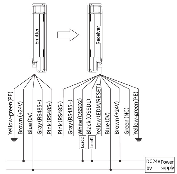
Transmission Line Sequence Diagram
The colors and functions of the transmission lines connected to the light curtain are shown in the table below:
| Cable | Pin | Wire Color | Function | Wiring Instructions |
| Transmitter Wire | 1 | Brown | 24 V Power Positive | Connect to DC power 24 V positive |
| 3 | Blue | 0 V power negative | Connect to the 0 V negative terminal of the DC power supply | |
| 2 | Grey | Configure RS485+ / Synchronize RS485+ | Refer to Wiring Diagram | |
| 4 | Pink | Configure RS485- / Synchronize RS485- | ||
| *PE | Yellow Green | PE Shielded Wire | Ground/GND | |
| Receiving Wire | 2 | Brown | 24 V Power Positive | Connect to DC power 24 V positive |
| 7 | Blue | 0 V power negative | Connect to the 0 V negative terminal of the DC power supply | |
| 5 | Grey | Configure RS485+ / Synchronize RS485+ | Refer to Wiring Diagram | |
| 6 | Pink | Configure RS485- / Synchronize RS485- | ||
| *PE | Yellow Green | PE Shielded Wire | Ground/GND | |
| 8 | Black | OSSD1 switching output terminal | Connect to switching signal input port 1 | |
| 1 | White | OSSD2 switching output terminal | Connect to switching signal input port 2 | |
| 4 | Yellow | EDM Detection and RESET Input | Refer to Wiring Diagram | |
| 3 | Green | - | Open wire |
How to Use
User Manual Download Link://in.misumi-ec.com/linked/material/mech/MSM1/CAD/2D/10311204649/Usermanual.zipSoftware Configuration
Debugging Tools
| Software Tools | Configuration Software |
| Tools | USB to RS485 Converter (driver can be obtained by contacting sales or technical support) |
| Computer | System Requirements: Windows XP or later, resolution 1280*720 or higher |
Software Installation (Standard Installation Green Version, Green Portable Version)
1. Select the portable software: E-LV4SLC Configuration
You can extract and use it directly after double-clicking the EXE file
Download link: //in.misumi-ec.com/linked/archive/im/E-LV4SLCInstallation-freesoftware.zip

2. Select the standard installation file: E-LV4SLC Configuration
Extract file and click the EXE file
Download link: //in.misumi-ec.com/linked/material/mech/MSM1/CAD/2D/10311204649/E-LV4SLCInstallation-freesoftware.zip

Select the language during installation

Show shortcut icon on desktop

Introduction to Software Usage
1. Communication Connection:
To prevent incorrect operation, this product can only communicate with the computer within 3 seconds after powering on.
Correctly connect the emitter or receiver of the light curtain to the power supply and the USB-to-RS485 converter (brown: 24 V DC, blue: 0 V DC, gray: RS485+, pink: RS485-).
Only one side of the light curtain can be connected for configuration at a time; do not connect both the emitter and receiver RS485 ports to the converter simultaneously. (Please refer to Chapter 4 Electrical Connections)

The connection steps are as follows:
(1) First, correctly connect the power supply of either the receiver or transmitter (Brown: 24 V DC, Blue: 0 V DC), and at the same time, properly connect the RS485 communication wires of the receiver or transmitter (Gray: RS485+, Pink: RS485-)
(2) Make sure the USB to RS485 converter is properly connected to the computer, and confirm the driver’s COM port number (for example, COM12)

Device Manager Example
2. Communication Connection Steps and Precautions:
1. (1) The light curtain is powered off ------] (2) Open the software and select the language ------] (3) Select the correct serial port number ------] (4) Click the [Open Serial Port] button ------] (5) Quickly power on the light curtain ------] The software will automatically switch to the working mode page
If the connection is not successful after 3 seconds, please check whether the serial port number is correct and whether the power supply and RS485 communication wires are properly connected, then repeat steps (1) ~ (5) .

Main Parameter Configuration Interface
3. Parameter Configuration Interface: (For light/line synchronization switching, both the transmitter and receiver must be modified at the same time)
1. Transmitter Parameter Configuration Interface:
The transmitter can be configured as needed: (1) Select the parameter option you want to modify ------] (2) Click the [Modify ***] button ------] (3) A [√] will be displayed to indicate the modification was successful.

Transmitter Parameter Configuration Interface
2. Receiver Parameter Configuration Interface:
Configure the receiver as needed: (1) Select the parameter option to be modified ------] (2) Click the [Modify ***] button ------] (3) A [√] indicates the item was successfully modified.

Receiver Parameter Configuration Interface
4. Communication Disconnection
After completing the configuration of the transmitter or receiver, the user can first disconnect the grating's 24 V DC power supply, then disconnect the RS485 communication cable to break the communication connection between the grating and the computer. At this point, the software configuration of the grating is complete, and it can be installed and used normally.
Grating Installation
The safety distance and installation height are two key factors to ensure the protective function of the safety grating. The safety distance must be calculated accurately, and the installation position of the grating must meet the requirements for both safety distance and installation height; otherwise, there is still a risk of accidents.
Installation Direction
The transmission line interfaces of the transmitter and receiver must face the same direction. The receiver must not be installed 180° opposite to the transmitter. The transmitter and receiver must be on the same plane, with the light-transmitting surfaces kept parallel and facing each other.

Installation Direction Diagram
Precautions
◆ When assembling, disassembling, or repairing the light curtain and cables, the power must be turned off first and the work should be performed by qualified personnel.
◆ Before each use, it is necessary to check whether the light curtain is properly controlling the equipment.
◆ Do not change the position of the light curtain arbitrarily during use.
◆ After replacing molds or fixtures, the safety distance and installation position of the light curtain must be adjusted by authorized personnel.
◆ During use, be careful not to let workpieces, tools, scrap, etc. collide with the light curtain or its plugs, cables, etc.
Selection Method
The distance to the hazard is determined by the minimum detectable object and response time of the selected area sensor. Common shaft spacing: 20 mm (⌀25 mm). However, when the distance to the hazard source is close, please select an optical axis pitch of 10 mm (⌀15 mm). When the distance to the hazard source is farther, you can also use the more cost-effective optical axis pitch of 40 mm (⌀45 mm).
When the distance to the hazard source is close
Detection object ⌀15 mm (finger detection)
Optical axis pitch 10 mm. Ultra-high safety type.

Detection object ⌀15 mm (finger detection)
Optical axis pitch 10 mm. Ultra-high safety type.

Common standard type
Detection body ⌀25 mm (manual detection)
Optical axis spacing 20 mm. Common types.
Detection body ⌀25 mm (manual detection)
Optical axis spacing 20 mm. Common types.

When the distance to the hazard source is relatively far
Detection body ⌀45 mm (arm, leg, body detection)
Optical axis pitch 40 mm. Please select this option when the installation location is far from the hazard source.
Detection body ⌀45 mm (arm, leg, body detection)
Optical axis pitch 40 mm. Please select this option when the installation location is far from the hazard source.

Specification Table
The default factory specification for the product is Light(Optical) synchronous communication connection mode
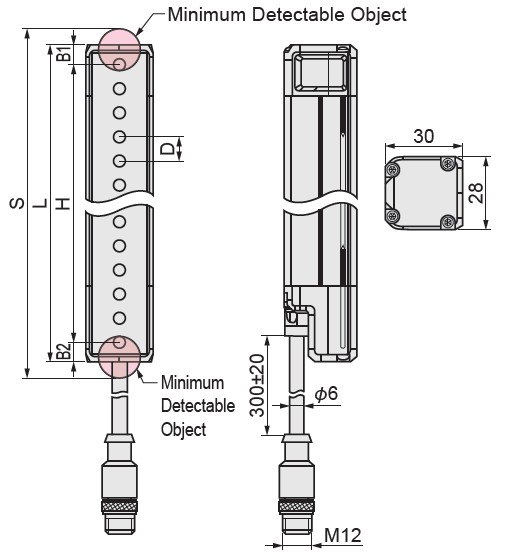

Grating Structure Dimensional Drawing
Detection Height H = (N-1) × Shaft Spacing, where N is the number of shafts
Protection Height S = N × Shaft Spacing + Resolution, where N is the number of shafts
Total Grating Height L = B1 + H + B2
*For the safe usage range design of blind-zone-free gratings, please refer to the protection height S.
| Part Number | - | Number of Optical Axes | - | Output Type |
| E-LV4SLC | - | 4 | - | N |
The default factory specification for the product is Light(Optical) synchronous communication connection mode
| Part Number | (3) Resolution (mm) | (4) Number of Optical Axes | (5) Output Type | Detection Height H (mm) | Component Dimension | Total Height L (mm) | Protection Height S (mm) | |
| ①Type | (2) Optical Axis Pitch D (mm) | H = ((4) - 1) × (2) | L = B1 + B2 + H | S = (4) × (2) + (3) | ||||
| E-LV4SLC | 10 | 15 | 16 to 100 | N (NPN output) / P (PNP output) | 150 to 990 | B1: 8 mm, B2: 8 mm | 166 to 1024 | 175 to 1015 |
| 20 | 25 | 8 to 52 | 140 to 1020 | B1: 8 mm, B2: 8 mm | 156 to 1036 | 185 to 1065 | ||
| 40 | 45 | 4 to 40 | 120 to 1560 | B1:18 mm, B2:18 mm | 156 to 1596 | 205 to 1645 | ||
| Type | Shaft Spacing | Number of Optical Axes | Output Type | Detection Height (mm) | Total height (mm) | Protection Height (mm) |
| D | H | L | S | |||
| E-LV4SLC | 10 | 16 | NPN: N PNP: P | 150 | 166 | 175 |
| 20 | 190 | 206 | 215 | |||
| 24 | 230 | 246 | 255 | |||
| 28 | 270 | 286 | 295 | |||
| 32 | 310 | 326 | 335 | |||
| 36 | 350 | 366 | 375 | |||
| 40 | 390 | 406 | 415 | |||
| 44 | 430 | 446 | 455 | |||
| 48 | 470 | 486 | 495 | |||
| 52 | 510 | 526 | 535 | |||
| 56 | 550 | 566 | 575 | |||
| 60 | 590 | 606 | 615 | |||
| 64 | 630 | 646 | 655 | |||
| 68 | 670 | 686 | 695 | |||
| 72 | 710 | 726 | 735 | |||
| 76 | 750 | 766 | 775 | |||
| 80 | 790 | 806 | 815 | |||
| 84 | 830 | 846 | 855 | |||
| 88 | 870 | 886 | 895 | |||
| 92 | 910 | 926 | 935 | |||
| 96 | 950 | 966 | 975 | |||
| 100 | 990 | 1006 | 1015 | |||
| 20 | 8 | 140 | 156 | 185 | ||
| 10 | 180 | 196 | 225 | |||
| 12 | 220 | 236 | 265 | |||
| 14 | 260 | 276 | 305 | |||
| 16 | 300 | 316 | 345 | |||
| 18 | 340 | 356 | 385 | |||
| 20 | 380 | 396 | 425 | |||
| 22 | 420 | 436 | 465 | |||
| 24 | 460 | 476 | 505 | |||
| 26 | 500 | 516 | 545 | |||
| 28 | 540 | 556 | 585 | |||
| 30 | 580 | 596 | 625 | |||
| 32 | 620 | 636 | 665 | |||
| 34 | 660 | 676 | 705 | |||
| 36 | 700 | 716 | 745 | |||
| 38 | 740 | 756 | 785 | |||
| 40 | 780 | 796 | 825 | |||
| 42 | 820 | 836 | 865 | |||
| 44 | 860 | 876 | 905 | |||
| 46 | 900 | 916 | 945 | |||
| 48 | 940 | 956 | 985 | |||
| 50 | 980 | 996 | 1025 | |||
| 52 | 1020 | 1036 | 1065 | |||
| 40 | 4 | 120 | 156 | 205 | ||
| 6 | 200 | 236 | 285 | |||
| 8 | 280 | 316 | 365 | |||
| 10 | 360 | 396 | 445 | |||
| 12 | 440 | 476 | 525 | |||
| 14 | 520 | 556 | 605 | |||
| 16 | 600 | 636 | 685 | |||
| 18 | 680 | 716 | 765 | |||
| 20 | 760 | 796 | 845 | |||
| 22 | 840 | 876 | 925 | |||
| 24 | 920 | 956 | 1005 | |||
| 26 | 1000 | 1036 | 1085 | |||
| 28 | 1080 | 1116 | 1165 | |||
| 30 | 1160 | 1196 | 1245 | |||
| 32 | 1240 | 1276 | 1325 | |||
| 34 | 1320 | 1356 | 1405 | |||
| 36 | 1400 | 1436 | 1485 | |||
| 38 | 1480 | 1516 | 1565 | |||
| 40 | 1560 | 1596 | 1645 |
Dimensional Drawing
Product Dimensions

Grating Structure Dimensional Drawing
Detection Height H = (N-1) × Shaft Spacing, where N is the number of shafts
Protection Height S = N × Shaft Spacing + Resolution, where N is the number of shafts
Total Grating Height L = B1 + H + B2
*For the safe usage range design of blind-zone-free gratings, please refer to the protection height S.
| Correspondence Table of Shaft Spacing and Structural Dimensions | |||
| Shaft Spacing D | B1 | B2 | Resolution |
| 10 mm | 8 mm | 8 mm | 15 mm |
| 20 mm | 8 mm | 8 mm | 25 mm |
| 40 mm | 18 mm | 18 mm | 45 mm |
Technical data
| Compliant with the following standards | IEC61508 SIL3 | ||
| Power supply | 24 V DC ±20% | ||
| Power | < 5 W | ||
| Shaft Spacing | 10 mm | 20 mm | 40 mm |
| Resolution | 15 mm | 25 mm | 45 mm |
| Number of Optical Axes | 16, 20,: , 160 | 8, 10,: , 80 | 4, 6,: , 40 |
| Protection Height | S = N × Optical Axis Spacing + Resolution, where N is the number of optical axes | ||
| Emission Light Source | 940 nm Infrared Light Source | ||
| Response Time | ≤ 2 × (N × 0.1+3) ms (N is the number of optical axes) | ||
| Safety Output (OSSD) | PNP transistor output, load current ≤ 200 mA, residual voltage ≤ 1 V (excluding voltage drop caused by cable extension), leakage current ≤ 0.1 mA; NPN transistor output, load current ≤ 200 mA, residual voltage ≤ 1 V (excluding voltage drop caused by cable extension), leakage current ≤ 0.1 mA. | ||
| Circuit Protection | Power Overvoltage Protection, Reverse Polarity Protection, Output Overcurrent Protection, Output Short Circuit Protection | ||
| Opposite Distance | 0.1 – 5 m | ||
| Light Interference Resistance | 10,000 Lux (incident angle I > 2.5°) | ||
| Grating Type | Through-beam | ||
| Synchronization Method | Optical Synchronization / Wire Synchronization (Optical synchronization is the default for delivery—no EDM, with automatic reset. Wire synchronization requires modification using dedicated software. For modification instructions, see [8. Software Configuration].) | ||
| Case Material | Aluminum | ||
| Product Accessories | Transmission cable: Emitter cable 4-core X1 X3.5 m, receiver cable: 8-core X1 X3.5 m, product body cable: 300 mm. | ||
| Mounting bracket: Side mounting, one set with freely rotatable combination | |||
| Cross-sectional Size | 30*28 mm | ||
| Protection Class | IP65 | ||
| Vibration Resistance | Frequency 10 Hz–55 Hz, amplitude 0.35±0.05 mm, 20 times each in X, Y, and Z directions | ||
| Impact resistance | 100 m/s2 (approximately 10 G), 16 ms pulse, 1000 times in each of the X, Y, and Z directions | ||
| Operating environment temperature | -10°C to 55°C (no condensation) | ||
| Storage environment temperature | -30°C to 70°C (no condensation) | ||
| Operating ambient humidity | Relative humidity < 85% at 20°C | ||
| TM (continuous operating time) | 20 years (ISO 13849-1) | ||
| Cable Specification Sheet | |||||
| Structure (configuration) | 5.8 Gray 4-core Shielded Cable (Brown, Gray, Blue, Pink) 40/0.08BS+250D+1.05*4C+4 Cotton Threads+AL+B96/0.10TC OD: 5.8 Gray | ||||
| Part Name (COMPONRNR) | A | ||||
| Conductor (Conductor) | Construction (AWG/mm) | 40/0.08BS+250D | |||
| Material | Bare copper | ||||
| OD/Cabling OD (mm) | 0.08±0.005 | ||||
| Insulation (Insulation) | Number of wires (NO of wire) | 4 | |||
| Conductor material (Material) | PVC 35P, heat resistant up to 105°C | ||||
| Conductor diameter (OD) mm | 1.1+0 -0.1 | ||||
| Average thickness (Thickness) | 0.2 | ||||
| Color | 1. Brown 2. Gray 3. Blue 4. Pink | ||||
| Shielding (Shield) | Aluminum foil Mylar (Aluminum/polyester) | AL. FACE OUTSIDE | |||
| Construction (N/mm) | Braiding: 96/0.10±3 | ||||
| Material | Tinned copper wire (TS) | ||||
| Shielding rate (coverage)% | 80% | ||||
| Binder (Binders) | Binder diameter (OD) mm | / | |||
| Material | / | ||||
| Color | / | ||||
| Jacket (Jacket) | Jacket Diameter (OD) mm | 5.8+0.1 mm | |||
| Material | 110P PVC semi-matte | ||||
| Color | Grey | ||||
| Average Thickness (MM) | 0.5 | ||||
| Marking (Marking) | AVVR 300/300 V 4*0.2 mm2 JB/T8734.4-2016 025 CE | ||||
| Attached Product Diagram (Diagram) |  | ||||
| Cable Specification Sheet | |||||
| Structure (configuration) | 5.8 mm Black 8-core Shielded Cable (White, Yellow, Green, Blue, Gray, Brown, Pink, Black) 40/0.08BS+250D+1.05*4C+4 Cotton Threads+AL+B96/0.10TC OD: 5.8 mm Black | ||||
| Part Name (COMPONRNR) | A | ||||
| Conductor (Conductor) | Construction (AWG/mm) | 40/0.08BS+250D | |||
| Material | Bare copper | ||||
| OD/Cabling OD (mm) | 0.08±0.005 | ||||
| Insulation (Insulation) | Number of wires (NO of wire) | 4 | |||
| Conductor material (Material) | PVC 35P, heat resistant up to 105°C | ||||
| Conductor diameter (OD) mm | 1.05+0 -0.1 | ||||
| Average thickness (Thickness) | 0.2 | ||||
| Color | 1. White 2. Yellow 3. Green 4. Blue 5. Gray 6. Brown 7. Pink 8. Black | ||||
| Shielding (Shield) | Aluminum foil Mylar (Aluminum/polyester) | AL. FACE OUTSIDE | |||
| Construction (N/mm) | Braiding: 96/0.10±3 | ||||
| Material | Tinned copper wire (TS) | ||||
| Shielding rate (coverage)% | 80% | ||||
| Binder (Binders) | Binder diameter (OD) mm | / | |||
| Material | / | ||||
| Color | / | ||||
| Jacket (Jacket) | Jacket Diameter (OD) mm | 5.8+0.1 mm | |||
| Material | 110P PVC | ||||
| Color | Black | ||||
| Average Thickness (MM) | 0.5 | ||||
| Marking (Marking) | AVVR 300/300 V 8*0.2 mm2 JB/T8734.4-2016 025 CE | ||||
| Attached Product Diagram (Diagram) |  | ||||