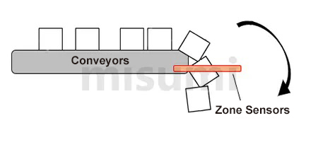
Area Sensor, General Purpose

Brand :
MISUMI
Caution
- For CE Certificate details, please refer to the updated PDF file on the webpage.
Product Description
This Video Explains the Operation of Area Sensors
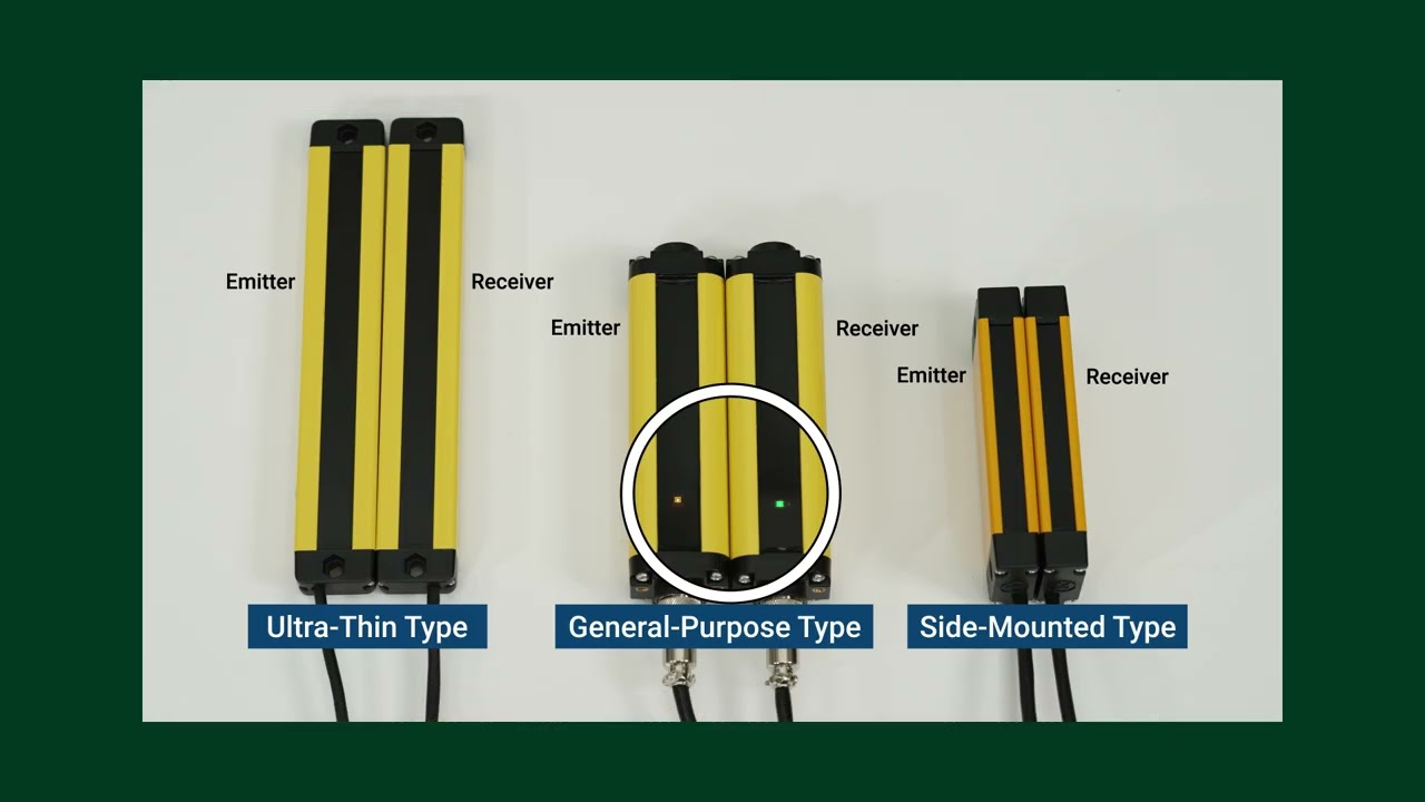
Product Overview
·Compact size, cross-sectional dimensions 35*27 mm
·Uses independent dual-circuit output control for high safety and reliability
·Short response time, fastest response time <1 ms
·Wide voltage supply DC24±20%
·Strong electromagnetic interference resistance, effectively withstands various electromagnetic interferences from motor equipment
·Uses line synchronization technology, strong resistance to optical interference
·Easy installation and simple operation
·Uses independent dual-circuit output control for high safety and reliability
·Short response time, fastest response time <1 ms
·Wide voltage supply DC24±20%
·Strong electromagnetic interference resistance, effectively withstands various electromagnetic interferences from motor equipment
·Uses line synchronization technology, strong resistance to optical interference
·Easy installation and simple operation
Product Comparison
Compare Old and New area sensor model:| Old E-ARS20-20-N | New E-MBF3SG20-20-N | |
| Sensing height | 380mm | 380mm |
| Sensing distance | 0.1~3m | 0.1~3m |
| Optical axis pitch | 20mm | 20mm |
| Light type | - | Infrared 940nm |
| Lenses | One side | Both side |
| Light beam angle | 15 Degree | 5 Degree |
| Response time | ≤5ms | 2.5ms |
| Supply voltage | DC24V ±10% | DC24V ±20% |
| Output | NPN | NPN |
| Number of output | 1 | 2 |
| Housing protection rating | - | IP54 |
| Electrical protection | Reverse Connection Protection/Output Short Circuit Protection | |
| Operating temperature | - | -10 to 55℃(No condensation) |
| Housing material | Aluminum alloy | Aluminum alloy |
| Anti-light interference | 10000Lux | 10000Lux (angle of incidence I > 5°) |
| Connection cable | Circular Connector 0.2mm2 PVC Length 2.5m | (GX12) × 1 (2pcs) 2.5m at emitter side, 3.5m at receiver side |
| Overall compare | • Economical choice. • Suitable for normal condition • Suitable for short detection distance | • Has lens in both transmitter and receiver • Better external light resistance • Smaller light beam, reduce influence of external reflective surface • Better protection with IP54 |
Dimensional Drawing
Product Drawings (Unit: mm)


| Part number | Item Size |
| A1 | Upper end cap |
| A2 | Lower End Cover + Aviation Terminal |
| B1 | Upper Blind Zone |
| B2 | Lower Blind Spot |
| D | Shaft Spacing |
| H | Protection Height |
| L | Total Height |
When D size is 10 mm: B1 size is 5 mm; B2 size is 30 mm.
When the D dimension is 20 mm: B1 dimension is 10 mm; B2 dimension is 35 mm.
When the D dimension is 40 mm: B1 dimension is 10 mm; B2 dimension is 35 mm.
L is the total height of the area sensor: L = height of upper and lower end caps + upper and lower blind spots + protection height
H is the protection height of the area sensor: H = (number of optical axes - 1) × optical axis pitch
Specification Overview
■ Specifications and Performance
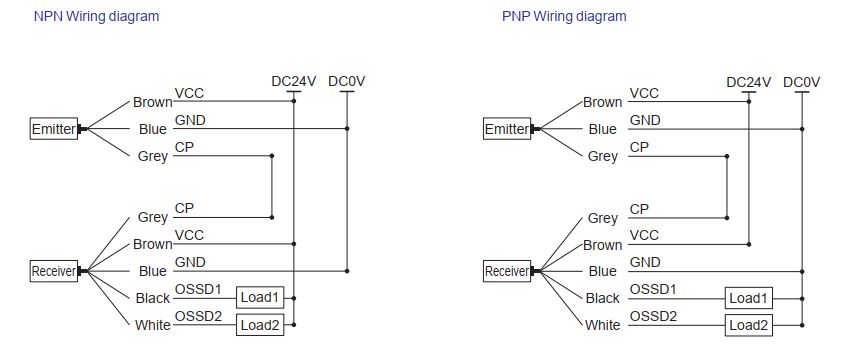
■ Output Circuit Diagram
■ Area Sensor Operating Status
Note: ○ indicates the indicator light is ON, ● indicates the indicator light is OFF
| Types | Optical Axis Pitch (10 mm) | Optical Axis Pitch (20 mm) | Optical Axis Pitch (40 mm) |
| Part number | E-MBF3SG10 | E-MBF3SG20 | E-MBF3SG40 |
| Item | |||
| Detection Height | 70 to 1960 mm | ||
| Casing Dimension | 35 × 27.7 mm | ||
| Detection Distance | 0 to 3 m | ||
| Optical Axis Pitch | 10/20/40 mm | ||
| Infrared Wavelength | 940 nm | ||
| Synchronization Method | Line Synchronization | ||
| Max. Power | ≤ 5W | ||
| Response Time | < 5 ms | ||
| Power Supply Voltage | 24 V DC ±20% | ||
| Safe Output (OSSD) | PNP transistor output: Load current ≤ 200 mA, residual voltage ≤ 1 V (excluding voltage drop caused by cable extension), leakage current ≤ 1 mA; NPN transistor output: Load current ≤ 200 mA, residual voltage ≤ 1 V (excluding voltage drop caused by cable extension), leakage current ≤ 1 mA. | ||
| Enclosure Protection Rating | IP 54 | ||
| Operating Temperature | -10 to 55°C (no condensation) | ||
| Storage Temperature | -20 to 70°C | ||
| Relative Humidity | 15% to 85% | ||
| Case Material | Aluminum | ||
| Light Interference Resistance | 10000Lux (Incidence Angle I > 5°) | ||
| Connection Method | (G × 12) × 1 (2 pcs) Emitter extension cable 2.5 m, receiver extension cable 3.5 m | ||
■ Output Circuit Diagram
| No. | Wire Color | Transmitter | Receiver | Wiring |
| 1 | Brown | +24 V | +24 V | Power Supply+ |
| 2 | Blue | 0V | 0V | Power Supply - |
| 3 | Grey | For Communication Use | For Communication Use | Transmitter and Receiver Interconnection |
| 4 | Black | / | NPN/PNP Output | Load Input Terminal 1 |
| 5 | White | / | NPN/PNP Output | Load Input 2 |
■ Area Sensor Operating Status
| Output Method | Area Sensor Status | Transmitter Indicator Light | Receiver Indicator Light | |
| Green Light | Green Light | Red Light | ||
| NPN NC | Optical Transmission | ○ | ○ | ● |
| Light Blocking | ○ | ● | ○ | |
| PNP NC | Optical Transmission | ○ | ○ | ● |
| Light Blocking | ○ | ● | ○ | |
Specification Table
The distance to the hazard is determined by the minimum detectable object and response time of the selected area sensor. Common shaft spacing: 20 mm (⌀25 mm). However, when the distance to the hazard source is short, please select a beam pitch of 10 mm (⌀15 mm). When the distance to the hazard source is greater, a more cost-effective beam pitch of 40 mm (⌀45 mm) can also be used.
 E-MBF3SG20-4 total height cannot be used in the calculation formula
Area sensor is used to detect objects, NOT suitable to the application where human safety should be secured.


| Part Number | - | Number of Optical Axes | - | Output Type | ||||
| E-MBF3SG | - | 4 | - | N |
| Part Number |  Number of Optical Axes Number of Optical Axes |  Output Type Output Type | Detection Height H (mm) | Component Dimension | Total Height L (mm) | |
 Type Type |  Optical Axis Pitch D Optical Axis Pitch D | H=(-1) × | L=A1+A2+B1+B2+H | |||
| E-MBF3SG | 10 | 8 to 100 | N(NPN Output)/ P(PNP Output) | 70 to 990 | A1:14 mm, A2:20 mm, B1:5 mm, B2:30 mm | 139 to 1059 |
| 20 | 4 to 50 | 60 to 980 | A1:14 mm, A2:20 mm, B1:10 mm, B2:35 mm | 139 to 1059 | ||
| 40 | 4 to 50 | 120 to 1960 | A1:14 mm, A2:20 mm, B1:10 mm, B2:35 mm | 199 to 2039 | ||
| Type | Optical Axis Pitch | Number of Optical Axes | Output Type | Detection Height (mm) | Total height (mm) |
| D | H | L | |||
| E-MBF3SG | 10 | 8 | NPN: N PNP: P | 70 | 139 |
| 12 | 110 | 179 | |||
| 16 | 150 | 219 | |||
| 20 | 190 | 259 | |||
| 24 | 230 | 299 | |||
| 28 | 270 | 339 | |||
| 32 | 310 | 379 | |||
| 36 | 350 | 419 | |||
| 40 | 390 | 459 | |||
| 44 | 430 | 499 | |||
| 48 | 470 | 539 | |||
| 52 | 510 | 579 | |||
| 56 | 550 | 619 | |||
| 60 | 590 | 659 | |||
| 64 | 630 | 699 | |||
| 68 | 670 | 739 | |||
| 72 | 710 | 779 | |||
| 76 | 750 | 819 | |||
| 80 | 790 | 859 | |||
| 84 | 830 | 899 | |||
| 88 | 870 | 939 | |||
| 92 | 910 | 979 | |||
| 96 | 950 | 1019 | |||
| 100 | 990 | 1059 | |||
| 20 | 4 | 60 | 139 | ||
| 6 | 100 | 179 | |||
| 8 | 140 | 219 | |||
| 10 | 180 | 259 | |||
| 12 | 220 | 299 | |||
| 14 | 260 | 339 | |||
| 16 | 300 | 379 | |||
| 18 | 340 | 419 | |||
| 20 | 380 | 459 | |||
| 22 | 420 | 499 | |||
| 24 | 460 | 539 | |||
| 26 | 500 | 579 | |||
| 28 | 540 | 619 | |||
| 30 | 580 | 659 | |||
| 32 | 620 | 699 | |||
| 34 | 660 | 739 | |||
| 36 | 700 | 779 | |||
| 38 | 740 | 819 | |||
| 40 | 780 | 859 | |||
| 42 | 820 | 899 | |||
| 44 | 860 | 939 | |||
| 46 | 900 | 979 | |||
| 48 | 940 | 1019 | |||
| 50 | 980 | 1059 | |||
| 40 | 4 | 120 | 199 | ||
| 6 | 200 | 279 | |||
| 8 | 280 | 359 | |||
| 10 | 360 | 439 | |||
| 12 | 440 | 519 | |||
| 14 | 520 | 599 | |||
| 16 | 600 | 679 | |||
| 18 | 680 | 759 | |||
| 20 | 760 | 839 | |||
| 22 | 840 | 919 | |||
| 24 | 920 | 999 | |||
| 26 | 1000 | 1079 | |||
| 28 | 1080 | 1159 | |||
| 30 | 1160 | 1239 | |||
| 32 | 1240 | 1319 | |||
| 34 | 1320 | 1399 | |||
| 36 | 1400 | 1479 | |||
| 38 | 1480 | 1559 | |||
| 40 | 1560 | 1639 | |||
| 42 | 1640 | 1719 | |||
| 44 | 1720 | 1799 | |||
| 46 | 1800 | 1879 | |||
| 48 | 1880 | 1959 | |||
| 50 | 1960 | 2039 |
 E-MBF3SG20-4 total height cannot be used in the calculation formulaArea sensor is used to detect objects, NOT suitable to the application where human safety should be secured.
Precautions
■ About installation
3. Precautions for Adjacent Installation
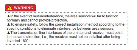
When two or more area sensor devices are installed close to each other, mutual interference between the area sensor devices can easily occur. As shown in Figure 3-1, the infrared light emitted by the transmitter unit of Product (1) may affect the receiver unit of Product (2) . This may interfere with the protective function of product (2), which means that operators may be at risk. Therefore, please install according to Figure 3-2. Avoid installing sensors for adjacent areas on the same side without a light-blocking partition, as the light emitted by the transmitter may easily reach the receiver of a neighboring set.

Figure 3-1 Diagram of Mutual Interference Between Emitter (1) and Emitter (2)

Figure 3-2 Installation diagram to prevent mutual interference between area sensors
4. Correct Installation Position When There Are Reflective Objects
If there are objects with smooth reflective surfaces around the area sensor device, such as metal plates, floors, ceilings, workpieces, covers, partitions, glass panels, etc., the installation position of the area sensor should be more than A (m) away from the reflective surface. The value of A can be obtained by calculation formula or found in coordinate chart 4-2. As shown in Figure 4-1, the cone has an aperture angle α, which is formed between the optical axis and the light beam located at the edge of the optical cone. Where α = the aperture angle of the light beam, L = the distance between the emitter and receiver, and L
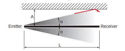
4-1 Reflective Object Interference Diagram
A (m) = L × tanα = L × 0.0875 (α = 5°)
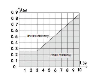
4-2 Coordinate Diagram of Installation Positions Where Reflective Objects Affect Area Sensors
(1) Bracket Installation


(2) Installation and Usage


3. Precautions for Adjacent Installation
When two or more area sensor devices are installed close to each other, mutual interference between the area sensor devices can easily occur. As shown in Figure 3-1, the infrared light emitted by the transmitter unit of Product (1) may affect the receiver unit of Product (2) . This may interfere with the protective function of product (2), which means that operators may be at risk. Therefore, please install according to Figure 3-2. Avoid installing sensors for adjacent areas on the same side without a light-blocking partition, as the light emitted by the transmitter may easily reach the receiver of a neighboring set.

Figure 3-1 Diagram of Mutual Interference Between Emitter (1) and Emitter (2)

Figure 3-2 Installation diagram to prevent mutual interference between area sensors
4. Correct Installation Position When There Are Reflective Objects
If there are objects with smooth reflective surfaces around the area sensor device, such as metal plates, floors, ceilings, workpieces, covers, partitions, glass panels, etc., the installation position of the area sensor should be more than A (m) away from the reflective surface. The value of A can be obtained by calculation formula or found in coordinate chart 4-2. As shown in Figure 4-1, the cone has an aperture angle α, which is formed between the optical axis and the light beam located at the edge of the optical cone. Where α = the aperture angle of the light beam, L = the distance between the emitter and receiver, and L
4-1 Reflective Object Interference Diagram
A (m) = L × tanα = L × 0.0875 (α = 5°)
| Protection Length L (m) | Maximum distance A (m) not available |
| 0.3 to 3 m | 0.262 m |
4-2 Coordinate Diagram of Installation Positions Where Reflective Objects Affect Area Sensors
● Please use within the specifications of this product. In addition, if this product is modified, its functionality and performance cannot be guaranteed.
● This product is developed/manufactured for use in industrial environments.
● Do not use outdoors.
● When this product is used to enhance human protection against hazards occurring around operating machinery, there may be regulations from relevant national or regional safety authorities. For more details, please contact the relevant department.
● When incorporating this product into specific machinery, please follow safety regulations that include proper usage methods, installation, operation, and maintenance items. Installers and responsible users are obligated to implement this product according to these items.
● This product may be damaged if subjected to excessive impact such as dropping. Please handle with care.
● Use this product only after considering possible malfunctions and implementing safety measures to prevent loss.
● Before operating this product, please confirm that its functions and performance operate normally according to the design specifications before use.
● When disposing of this product, please treat it as industrial waste.
● This product is developed/manufactured for use in industrial environments.
● Do not use outdoors.
● When this product is used to enhance human protection against hazards occurring around operating machinery, there may be regulations from relevant national or regional safety authorities. For more details, please contact the relevant department.
● When incorporating this product into specific machinery, please follow safety regulations that include proper usage methods, installation, operation, and maintenance items. Installers and responsible users are obligated to implement this product according to these items.
● This product may be damaged if subjected to excessive impact such as dropping. Please handle with care.
● Use this product only after considering possible malfunctions and implementing safety measures to prevent loss.
● Before operating this product, please confirm that its functions and performance operate normally according to the design specifications before use.
● When disposing of this product, please treat it as industrial waste.
Example of Use
For Protection
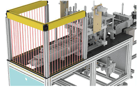
For Protection
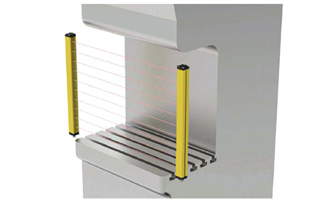
For Blanking Detection