Area Sensor, Ultra-Thin Type

Brand :
MISUMI
Caution
Product Description
Dimension of upper and lower covers A = 12mm
When D = 10mm: B1 = 5mm; B2 = 5mm.
When D = 20mm: B1 = 10mm; B2 = 10mm.
When D = 40mm: B1 = 10mm; B2 = 30mm.
L is the overall height of area sensor: L = height of upper and lower covers + upper and lower blind spots + protection height
H is the protection height of area sensor: H = (number of optical axes - 1) × optical axis pitch
Product Overview
• Ultra-thin size, the overall size is only 28*13mm
• Short response time, the fastest response time <1ms
• Wide voltage power supply DC24±20%
• Strong anti-electromagnetic interference ability, can effectively resist various electromagnetic interference effects of motor equipment
• Adopt line synchronization technology, strong anti-light interference ability
• Easy installation and simple operation
Product Comparison
Compare Old and New area sensor model| Old E-ARST20-20-N | New E-MSF3SG20-20-N | |
| Sensing height | 380mm | 380mm |
| Sensing distance | 0.1~3m | 0.1~2.5m |
| Optical axis pitch | 20mm | 20mm |
| Light type | - | Infrared 940nm |
| Lenses | One side | Both side |
| Light beam angle | 15 Degree | 5 Degree |
| Response time | ≤5ms | 2.5ms |
| Supply voltage | DC24V ±10% | DC24V ±20% |
| Output | NPN | NPN |
| Number of output | 1 | 1 |
| Housing protection rating | - | IP54 |
| Electrical protection | Reverse Connection Protection/Output Short Circuit Protection | |
| Operating temperature | - | -10 to 55℃(No condensation) |
| Housing material | Aluminum alloy | Aluminum alloy |
| Anti-light interference | 10000Lux | 10000Lux (angle of incidence I > 5°) |
| Connection cable | Wire lead-out type (2.5m) | Wire lead-out type (2m) |
| Overall compare | • Economical choice. • Suitable for normal condition • Suitable for short detection distance | • Has lens in both transmitter and receiver • Better external light resistance • Smaller light beam, reduce influence of external reflective surface • Better protection with IP54 |
Dimensional Drawing
(Unit: mm)
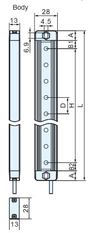

| Model | Item Dimension |
| A | Upper and lower covers |
| B1 | Upper blind spot |
| B2 | Lower blind spot |
| D | Optical axis pitch (10mm/20mm/40mm) |
| H | Protection height of area sensor |
| L | Overall height of area sensor |
When D = 10mm: B1 = 5mm; B2 = 5mm.
When D = 20mm: B1 = 10mm; B2 = 10mm.
When D = 40mm: B1 = 10mm; B2 = 30mm.
L is the overall height of area sensor: L = height of upper and lower covers + upper and lower blind spots + protection height
H is the protection height of area sensor: H = (number of optical axes - 1) × optical axis pitch
Specification Overview
■Specifications and performance
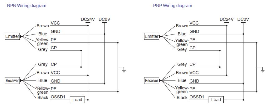
■Output circuit diagram
■Area sensor operating status
Note:○ indicates that an indicator is on, while ● indicates that an indicator is off
| Type | Optical axis pitch (10mm) | Optical axis pitch (20mm) | Optical axis pitch (40mm) |
| Model | E-MSF3SG10 | E-MSF3SG20 | E-MSF3SG40 |
| Item. | |||
| Sensing height | 104~1304mm | ||
| Housing dimensions | 28×13mm | ||
| Sensing distance | 0.1~2.5m | ||
| Optical axis pitch | 10/20/40mm | ||
| Infrared wavelength | 940nm | ||
| Synchronization type | Line synchronization | ||
| Maximum power | ≤5W | ||
| Response time | <5ms | ||
| Supply voltage | DC24V±20% | ||
| Safety output (OSSD) | PNP transistor output: load current ≤ 200mA, residual voltage ≤ 1V (except for voltage drop caused by cable extension), and leakage current ≤ 1mA; NPN transistor output: load current ≤ 200mA, residual voltage ≤ 1V (except for voltage drop caused by cable extension), and leakage current ≤ 1mA. | ||
| Housing protection rating | IP 54 | ||
| Operating temperature | -10~55℃(No condensation) | ||
| Storage temperature | -20~70℃ | ||
| Relative humidity | 15%~85% | ||
| Housing material | Aluminum alloy | ||
| Anti-light interference | 10000Lux (angle of incidence I > 5°) | ||
| Connection mode | Wire lead-out type (2m) | ||
■Output circuit diagram

| NO. | Cable Color | Emitter side | Receiver side | Wiring |
| 1 | Brown | +24V | +24V | Power Supply+ |
| 2 | Blue | 0V | 0V | Power Supply- |
| 3 | Grey | Communication | Communication | Interconnection between emitter and receiver |
| 4 | Black | / | NPN/PNP Output | Load input side |
| 5 | Yellow-Green | PE shielded wire | Grounding | |
■Area sensor operating status
| Output mode | Area sensor status | Emitter indicator | Receiver indicator | |
| Green | Green | Red | ||
| NPN NC | Light-ON | ○ | ○ | ● |
| Dark-ON | ○ | ● | ○ | |
| PNP NC | Light-ON | ○ | ○ | ● |
| Dark-ON | ○ | ● | ○ | |
Specification Table
The distance to the hazard source is determined by the minimum detection body and response time of the selected area sensor. A common optical axis spacing of 20 mm (ø25 mm) is typically used. However, for closer distances to the hazard source, an optical axis spacing of 10 mm (ø15 mm) is recommended. Conversely, for longer distances to the hazard source, a cost-effective option is to use an optical axis spacing of 40 mm (ø45 mm).


 Type Type | - |  Number of optical axes Number of optical axes | - |  Output Type Output Type |
| E-MSF3SG | - | 4 | - | N |
| Part Number | Number of optical axes | Output type | Protection Height H(mm) | Component size | Overall Height L(mm) | |
| Type |  Optical axis pitch D(mm) Optical axis pitch D(mm) | H=(-1)× | L=2xA+B1+B2+H | |||
| E-MSF3SG | 10 | 8~28 | N(NPN Output) P(PNP Output) | 70~270 | A:12mm,B1:5mm,B2:5mm | 104~304 |
| 20 | 4~28 | 60~540 | A:12mm,B1:10mm,B2:10mm | 104~584 | ||
| 40 | 4~32 | 120~1240 | A:12mm,B1:10mm,B2:30mm | 184~1304 | ||
| Type | Optical axis pitch | Number of optical axes | Output Type | Protection Height (mm) | Overall Height(mm) |
| D | H | L | |||
| E-MSF3SG | 10 | 8 | NPN: N PNP: P | 70 | 104 |
| 12 | 110 | 144 | |||
| 16 | 150 | 184 | |||
| 20 | 190 | 224 | |||
| 24 | 230 | 264 | |||
| 28 | 270 | 304 | |||
| 8 | 70 | 104 | |||
| 12 | 110 | 144 | |||
| 16 | 150 | 184 | |||
| 20 | 190 | 224 | |||
| 24 | 230 | 264 | |||
| 28 | 270 | 304 | |||
| 20 | 4 | 60 | 104 | ||
| 6 | 100 | 144 |
| Type | Optical axis pitch | Number of optical axes | Output Type | Protection Height (mm) | Overall Height (mm) |
| D | H | L | |||
| E-MSF3SG | 20 | 8 | NPN: N PNP: P | 140 | 184 |
| 10 | 180 | 224 | |||
| 12 | 220 | 264 | |||
| 14 | 260 | 304 | |||
| 16 | 300 | 344 | |||
| 18 | 340 | 384 | |||
| 20 | 380 | 424 | |||
| 22 | 420 | 464 | |||
| 24 | 460 | 504 | |||
| 26 | 500 | 544 | |||
| 28 | 540 | 584 | |||
| 40 | 4 | 120 | 184 | ||
| 6 | 200 | 264 |
| Type | Optical axis pitch | Number of optical axes | Output Type | Protection Height (mm) | Overall Height(mm) |
| D | H | L | |||
| E-MSF3SG | 40 | 8 | NPN: N PNP: P | 280 | 344 |
| 10 | 360 | 424 | |||
| 12 | 440 | 504 | |||
| 14 | 520 | 584 | |||
| 16 | 600 | 664 | |||
| 18 | 680 | 744 | |||
| 20 | 760 | 824 | |||
| 22 | 840 | 904 | |||
| 24 | 920 | 984 | |||
| 26 | 1000 | 1064 | |||
| 28 | 1080 | 1144 | |||
| 30 | 1160 | 1224 | |||
| 32 | 1240 | 1304 |
Precautions
■About installation 3. Precautions for adjacent installation
When two or more sets of area sensors are installed adjacent to each other, mutual interference is likely to occur between the sensors, as shown in Fig. 3-1, where infrared light from the emitter of product ① may affect the receiver of product ②. This may interfere with the protective function of product ②, putting the operator in danger, so the installation method shown in Figure 3-2 must be followed. That is, in the absence of a light-blocking plate, avoid installing adjacent area sensors on the same side. Otherwise, the light emitted from the emitter can easily fall on another adjacent receiver.

Figure 3-1 Illustration of interference between emitter ① and emitter ②
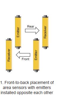
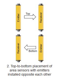
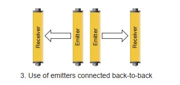
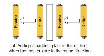
Figure 3-2 Illustration of installation positions for prevention of mutual interference between area sensors
4. Correct installation position in the presence of reflective objects
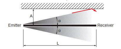
If the area sensor is surrounded by any objects with smooth reflective surfaces, such as metal plates, floors, ceilings, machined parts, coverings, baffles, and glass panels, the area sensor must be installed at a distance greater than A (m) from the reflective surfaces, and the value of A can be derived from the formula or found in the coordinate diagram Figure 4-2. As shown in Figure 4-1, the cone has an aperture angle α that is formed between the optical axis and the light beam at the edge of the optical cone. Where α = aperture angle of light beam, L = distance between emitter and receiver, and L < the maximum transmitting distance of area sensor.
4-1 Illustration of interference from reflective object
A (m)=L×tanα=L×0.0875(α=5°)
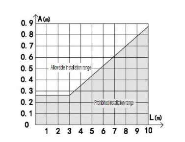
4-2 Coordinate diagram of installation positions withrespect to impact of reflective objects on area sensor
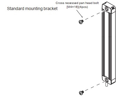
(1) Bracket Installation

When two or more sets of area sensors are installed adjacent to each other, mutual interference is likely to occur between the sensors, as shown in Fig. 3-1, where infrared light from the emitter of product ① may affect the receiver of product ②. This may interfere with the protective function of product ②, putting the operator in danger, so the installation method shown in Figure 3-2 must be followed. That is, in the absence of a light-blocking plate, avoid installing adjacent area sensors on the same side. Otherwise, the light emitted from the emitter can easily fall on another adjacent receiver.

Figure 3-1 Illustration of interference between emitter ① and emitter ②


Figure 3-2 Illustration of installation positions for prevention of mutual interference between area sensors

4. Correct installation position in the presence of reflective objects
If the area sensor is surrounded by any objects with smooth reflective surfaces, such as metal plates, floors, ceilings, machined parts, coverings, baffles, and glass panels, the area sensor must be installed at a distance greater than A (m) from the reflective surfaces, and the value of A can be derived from the formula or found in the coordinate diagram Figure 4-2. As shown in Figure 4-1, the cone has an aperture angle α that is formed between the optical axis and the light beam at the edge of the optical cone. Where α = aperture angle of light beam, L = distance between emitter and receiver, and L < the maximum transmitting distance of area sensor.

4-1 Illustration of interference from reflective object
A (m)=L×tanα=L×0.0875(α=5°)
| Protective length L(m) | Allowable installation distance A(m) |
| 0.3 to 2.5m | 0.262m |

4-2 Coordinate diagram of installation positions withrespect to impact of reflective objects on area sensor

■ Other precautions of use:
• Please use the product within its specifications. In addition, the function and performance of the product cannot be guaranteed if modified.
• This product is developed and manufactured for use in an industrial environment.
• Do not use the product outdoors.
• When using the product to improve the protection of objects from the hazards around the machine to which it is applied, follow the regulations of the relevant safety authorities of the country or region. For details, please consult the appropriate authorities.
• When applying the product to a specific machine, follow the appropriate use method and safety regulations for installation, operation, and maintenance items. The installation personnel and the personnel in charge of the use of the product shall be responsible for applying the product based on these items.
• Be aware that the product may be damaged if subjected to excessive impact caused by events such as a fall.
• Use the product with consideration for the abnormalities that may occur to the product and with the appropriate safety measures in place to prevent loss.
• Before putting the product into operation, check that its functions.
• Dispose of the product as industrial waste when it is scrapped.
Example of Use
