Double Disc Couplings Clamping Type

Brand :
MISUMI
Caution
Product Description
New at MISUMI? Get upto ₹10,000 Discount* on Your First Order. Click to Register Now

This is an economy item, The price is cheaper than the MISUMI standard product.
Product Overview of Flexible Shaft Couplings
Flexible Shaft Couplings is made of several sets of discs (stainless steel sheet) bolted staggered with two coupling halves, each set of discs by several pieces of stacked set.
The Flexible Shaft Couplings relies on the elastic deformation of the disc to compensate for the relative displacement of the two shafts connected, is a high-performance flexible coupling with strong metal components.
It is characterized by compact structure, zero backlash, high strength, long service life, no rotating clearance, unaffected by temperature and oil, acid and alkali resistant and corrosion resistant.
Applicable motor types: Recommended for servo motors, stepper motors and general motors.
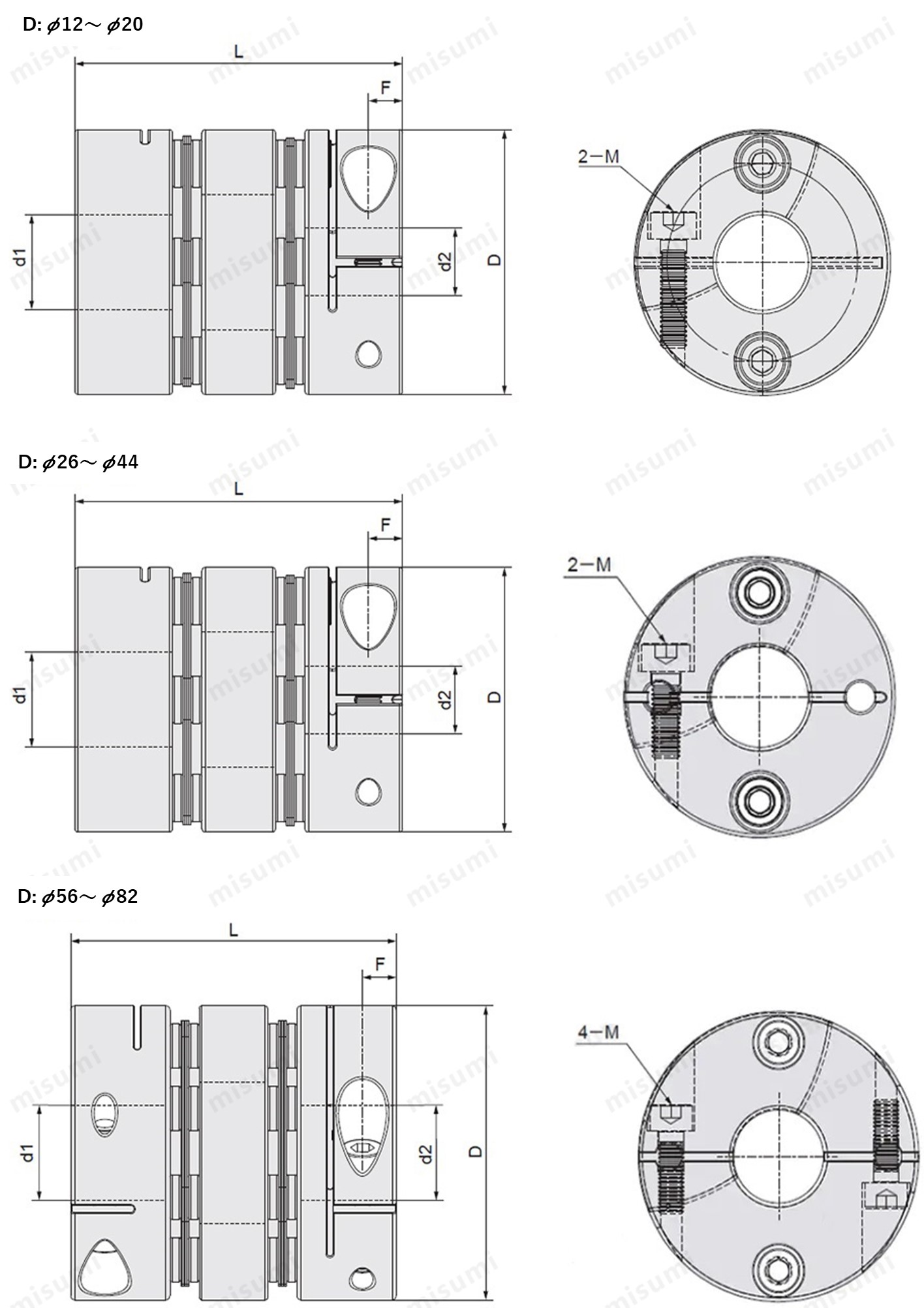
Dimensional Drawing of Flexible Shaft Couplings
Clamping Type
Material table

Material table
| Type | Part |  Material Material |  Surface Treatment Surface Treatment |  Accessory Accessory |
| E-LMCPW | Hub | Aluminum Alloy | Clear Anodize | Hex Socket Clamp Screw |
| Disc | Stainless Steel | - |
Specification Table of Flexible Shaft Couplings
Flexible Shaft Couplings, Please follow the selection steps ~
~  to select the part no. Please specify the shaft holediameter within the range of d1≤d2.
 ~
~  to select the part no. Please specify the shaft holediameter within the range of d1≤d2.
Part No.(Type· D) D) | - |  d1 d1 | - | d2 |
| E-LMCPW12 | - | 3 | - | 5 |
| E-LMCPW20 | - | 4 | - | 6 |
| Part No. | d1、d2Shaft Hole Dia.(d1≤d2) | ||||||||||||||||||||||||||||||
| Type | D | ||||||||||||||||||||||||||||||
| E-LMCPW | 12 | *3 | *4 | *5 | |||||||||||||||||||||||||||
| 16 | *3 | *4 | *5 | 6 | |||||||||||||||||||||||||||
| 19 | *3 | *4 | *5 | 6 | 6.35 | 7 | 8 | ||||||||||||||||||||||||
| 20 | *3 | *4 | *5 | 6 | 6.35 | 7 | 8 | ||||||||||||||||||||||||
| 26 | *5 | 6 | 6.35 | 7 | 8 | 9 | 9.525 | 10 | 11 | 12 | 14 | ||||||||||||||||||||
| 29 | *5 | 6 | 6.35 | 7 | 8 | 9 | 9.525 | 10 | 11 | 12 | 14 | ||||||||||||||||||||
| 32 | *5 | 6 | 6.35 | 8 | 9 | 9.525 | 10 | 11 | 12 | 12.7 | 14 | 15 | |||||||||||||||||||
| 33 | *5 | 6 | 6.35 | 8 | 9 | 9.525 | 10 | 11 | 12 | 12.7 | 14 | 15 | 16 | ||||||||||||||||||
| 34 | *5 | 6 | 6.35 | 8 | 9 | 9.525 | 10 | 11 | 12 | 12.7 | 14 | 15 | 16 | ||||||||||||||||||
| 39 | 8 | 9 | 9.525 | 10 | 11 | 12 | 12.7 | 14 | 15 | 16 | 17 | 18 | 19 | ||||||||||||||||||
| 44 | 8 | 9 | 9.525 | 10 | 11 | 12 | 12.7 | 14 | 15 | 16 | 17 | 18 | 19 | 20 | 22 | ||||||||||||||||
| 56 | 10 | 12 | 14 | 15 | 16 | 17 | 18 | 19 | 20 | 22 | 24 | 25 | 28 | 30 | 32 | ||||||||||||||||
| 68 | 12 | 14 | 15 | 16 | 17 | 18 | 19 | 20 | 22 | 24 | 25 | 28 | 30 | 32 | 35 | 38 | |||||||||||||||
| 82 | 17 | 18 | 19 | 20 | 22 | 24 | 25 | 28 | 30 | 32 | 35 | 38 | 40 | 42 | |||||||||||||||||
d1, d2* size products without keyway holes.
| Part No. | L | F | Clam Screw | Permissible torque (N·m) | Permissible eccentricity (mm) | Static Torsional Spring Constant (N·m/rad) | Maximum Rotational Speed (r/min) | Compensation Coefficient | Mass (g) | ||
| Type | D | M | Tightening torque N.m | ||||||||
| E-LMCPW | 12 | 15.9 | 2.2 | M1.6 | 0.23~0.28 | 0.25 | 0.03 | 133 | 10000 | 1 | 3.7 |
| 16 | 23 | 2.6 | M2 | 0.4~0.5 | 0.6 | 0.05 | 255 | 10000 | 1 | 10 | |
| 19 | 27 | 3.2 | M2.5 | 1 | 1 | 0.12 | 700 | 10000 | 1 | 14 | |
| 20 | 28.8 | 3.2 | M2.5 | 1 | 1 | 0.10 | 550 | 10000 | 1 | 19 | |
| 26 | 35 | 4 | M3 | 1.5 | 2 | 0.15 | 1850 | 10000 | 1 | 37 | |
| 29 | 34.3 | 4 | M3 | 1.5 | 2 | 0.15 | 1200 | 10000 | 1 | 43 | |
| 32 | 41 | 4 | M3 | 1.5 | 6 | 0.17 | 2850 | 10000 | 1 | 67 | |
| 33 | 40 | 4 | M3 | 1.5 | 6 | 0.20 | 1500 | 10000 | 1 | 60 | |
| 34 | 45 | 5 | M4 | 3.5 | 6 | 0.17 | 4050 | 10000 | 1 | 77 | |
| 39 | 50 | 5.2 | M4 | 3.5 | 13 | 0.22 | 9000 | 10000 | 1 | 118 | |
| 44 | 50 | 5.2 | M4 | 3.5 | 15 | 0.22 | 10000 | 10000 | 1 | 144 | |
| 56 | 64 | 6.3 | M5 | 8 | 28 | 0.27 | 25000 | 10000 | 1 | 318 | |
| 68 | 75 | 7.7 | M6 | 13 | 60 | 0.31 | 35000 | 9000 | 1 | 492 | |
| 82 | 98 | 9.8 | M8 | 28 | 100 | 0.55 | 70000 | 8000 | 1 | 1013 | |
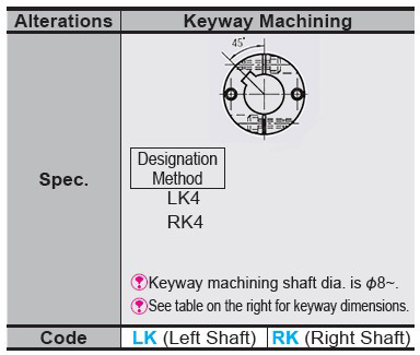
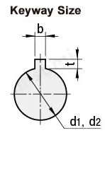
Alterations of Flexible Shaft Couplings


| Shaft Hole Dia. d1 · d2 | b(Keyway Width) | t Keyway Depth | Keyway Nominal Dim. b X h | |
| LK | RK | |||
| 6 ~ 7.9 | 2 | 2 | 1 | 2x2 |
| 8~10 | 3 | 3 | 1.4 | 3x3 |
| 11~12 | 4 | 4 | 1.8 | 4x4 |
| 13~17 | 5 | 5 | 2.3 | 5x5 |
| 18~22 | 6 | 6 | 2.8 | 6x6 |
| 23~30 | 8 | 8 | 3.3 | 8x7 |
| 31~38 | 10 | 10 | 3.3 | 10x8 |
| 39~44 | 12 | 12 | 3.3 | 12x8 |
Product Features of Flexible Shaft Couplings
■Main characteristics of Flexible Shaft Couplings
1. Strong capability to compensate for misalignment of two shafts, offering twice the angular displacement compared to Jaw couplings, lower reactionary forces during radial displacement, high flexibility, and allows for certain axial,radial, and angular displacements.
2. Provides significant vibration damping effects, operates without noise, and wear-free.
3. Can safely operate under conditions of shock and vibration.
4. High transmission efficiency, up to 99.86%, particularly suitable for medium and high-speed, high-power transmission.
5. Simple structure, lightweight, small volume, and convenient for assembly and disassembly. Installation and removal can be done without moving the machine (refers to the type with an intermediate shaft) and does not require lubrication.
6. Can accurately transmit rotational speed, operates without slip, suitable for the transmission of precision machinery.
Example Use of Flexible Shaft Couplings

Precautions of Flexible Shaft Couplings
■Calibration adjustment of Flexible Shaft Couplings
1. The coupling allows transmission of axis deviation, rotation angle and torque, but if the axis deviation exceeds the allowable value, vibration may occur or the lifespan will be drastically reduced. Please be sure to make corrections.
2. Axial deviation includes eccentricity (parallel error of two axes), declination (angular error of two axes), and axial amplitude (axial movement of the axes).
Perform calibration adjustment for the shaft so that the shaft center deviation is below the allowable value specified in the product dimensions and performance table.
3. The axial deviation tolerance values stated in the dimensions and performance tables refer to the situation when one of eccentricity, declination, and axial amplitude occurs individually. If two or moreaxial deviations occur simultaneously, the respective allowable values are reduced by half.
4. Axial deviation not only occurs when assembling the device, but is also a major cause of vibration, thermal expansion, and bearing wear during operation.
It is recommended that the axis deviation be set to less than 1/3 of the allowable value.