(!)NOTE : Windows 7 users won’t be able to use some latest features of eCatalog/WOS since Microsoft is ending support for Windows 7 on 14 Jan, 2020. Please upgrade your system for uninterrupted services.
- Due to an increase in demand, the lead time of some of the electrical items from our eCatalogue has increased abnormally and may cause delays in delivery or order suspension. We apologize for the inconvenience and appreciate your kind understanding. Once the supply will get normalized, we will update the same.
Specification/Dimensions
-
Table O.D.(Ø)
-
Load Capacity (Range)(N)
- 5~30
- 30.1~50
- 100.1~
-
Table Feeding Method
- Worm Gear
- Ball Screw
-
Minimum Resolution (Angle)(deg)
-
Load Capacity(N)
-
Part Number
-
Cable
- 2
- 4
-
type
- E-RMPG
-
CAD
- 2D
- 3D
Days to Ship
-
- All
- 5 Day(s) or Less
Specify Alterations
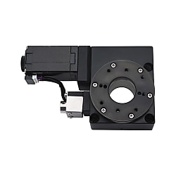
Motorized Rotary Stages Worm Gear Type
Click this image to zoom it.
Move the mouse over or click the image to zoom


- Volume Discount
Copy Part Number URL to Clipboard
The part number URL has been copied into your clipboard.-
- Starting From :
- 34,474₹/Unit

-
- Order Qty :
-
-
- Total Price :
- ---
-
- Days to ship :
- ---
Select part number to Order Now/ Add to Cart
Feature 2: Optimized structure and low prices are achieved through local production.
Feature 3: Quick disassembling is achieved by adding dowel holes to the upper and lower seats of the stage.
Feature 4: Standard equipped driver is applicable to dual pulse and pulse + direction control, which can be used under multiple working conditions.

 Material Aluminum Alloy
 Surface Treatment Black Anodized
| Part Number |  Driver Driver |  Cable Cable | Mechanical Specification | Accuracy Specification | Sensor | ||||||||
 Type Type |  No. No. | Stage Surface (mm) | Travel Distance (°) | Load Capacity (N) | Weight (kg) | Maximum Speed (°/sec) | One-Way Positioning Accuracy | Repetitive Positioning Accuracy | Parallelism (μm) | Limit Sensor | Origin Sensor (ORG1) | ||
| E-RMPG | 40 | A | φ39 | 360 | 29.4 | 0.5 | 25 | Within 0.15° | Within ±0.08° | Within 50 | Not Provided | Provided | |
| 60 | 2 (2m cable) | φ60 | 39.2 | 0.9 | 15 | ||||||||
| 80 | φ79 | 39.2 | 1.1 | 15 | |||||||||
| 100 | 4 (4m cable) | φ99 | 196 | 1.9 | 25 | ||||||||
| 120 | φ119 | 196 | 2.2 | 25 | |||||||||
■ Universal Specifications
| No. | 40 | 60 | 80 | 100 | 120 | |
| Deceleration Ratio | 1/120 | 1/180 | 1/180 | 1/120 | 1/120 | |
| Guide | Deep Groove Ball Bearing | |||||
| Motor | Type | 2-Phase Standard Stepper Motor 1.3A/Phase | 2-Phase High Torque Stepper Motor 1.3A/Phase | 2-Phase Standard Stepper Motor 2.0A/Phase | 2-Phase Standard Stepper Motor 2.0A/Phase | |
| Step Angle | 1.8° | |||||
| Resolution (Pulse) Full | ≒0.015° | ≒0.01° | ≒0.01° | ≒0.015° | ≒0.015° | |
| Driver | Power Voltage | DC12~50V | ||||
| Output Current | 0.1~2.2A | |||||
| Pulse Signal Voltage | 5~24V | |||||
| Subdivision | 200~51200 | |||||
| Connector | Part Number | HR10A-10R-12P (HIROSE) | ||||
| Receiving Side Part Number | HR10A-10P-12S (HIROSE) | |||||
| Sensor Substrate | Limit Sensor | Not Provided | ||||
| Origin Sensor | Provided | |||||
| Power Voltage | DC24V±10% | |||||
| Sensor Type | Photomicro Sensor EE-SX4320 (OMRON) | |||||
| Control Output | NPN Open Collector Output | |||||
| Output Logic | When detecting (shading): output transistor OFF (non-conductive) | |||||

* 1. The cable in the dotted box is 2m or 4m cable
The applicable driver supports dual pulse and pulse + direction control. For the mounting dimensions and 3D download, reference can be made to C-DR42A
. Compared with C-DR42A, the applicable driver has the same external dimensions, but comes with an additional dual-pulse control function.
Operating environment: 10~50℃, 20~70% RH (without condensation)
Recommended operating environment: 22±5℃, 20~70%RH (without condensation)
Please avoid using this positioning stage in the following environments
① Dusty environment (especially metal powder)
② Environment with direct sunlight and thermal radiation
③ Environment near fire sources
④ Environment containing corrosive gases and flammable gases
⑤ Environment with splashing water and oil
⑥ Environment with strong vibration and impact⑦ Environment containing organic solutions and salt
■Positioning stage maintenance
A uniform maintenance standard is not available, and the maintenance method is subject to the type of grease and operating environment. Based on the driving conditions and guide types, make sure to check the grease once a month.
| Electronics/Home Appliance | Automotive | Medical | ||
 |  |  | ||
| Smart Phones | Semiconductor | Lithium battery | ||
 |  |  |
| Economy series X-Axis Motorized Positioning Stages | Economy series XY-Axis Motorized Positioning Stages | Economy series Z-Axis Motorized Positioning Stages |
 |  |  |
| Representative model: C-XMBS420-L-A-2 | Representative model: C-XYMBS420-L-A-2 | Representative model: C-ZMBS420-L-A-2 |
Part Number
- Incomplete part number.
Please use left hand selections to complete a part number.
| Part Number |
|---|
| E-RMPG40-A-2 |
| E-RMPG40-A-4 |
| E-RMPG60-A-2 |
| E-RMPG60-A-4 |
| E-RMPG80-A-2 |
| E-RMPG80-A-4 |
| E-RMPG100-A-2 |
| E-RMPG100-A-4 |
| E-RMPG120-A-2 |
| E-RMPG120-A-4 |
| Part Number | Price | Minimum Order Qty. | Volume Discount | Days to Ship | Table O.D. (Ø) | Load Capacity (Range) (N) | Table Feeding Method | Minimum Resolution (Angle) (deg) | Load Capacity (N) | Max. Speed (mm/sec) | Part Number | Cable |
|---|---|---|---|---|---|---|---|---|---|---|---|---|
₹ 34,474.00 | 1 Piece(s) | Available | 5 Day(s) | 40 | 5~30 | Ball Screw | 0.015 | 29.4 | 25 | E-RMPG40 | 2 | |
₹ 35,157.00 | 1 Piece(s) | Available | 5 Day(s) | 40 | 5~30 | Ball Screw | 0.015 | 29.4 | 25 | E-RMPG40 | 4 | |
₹ 34,936.00 | 1 Piece(s) | Available | 5 Day(s) | 60 | 30.1~50 | Ball Screw | 0.01 | 39.2 | 15 | E-RMPG60 | 2 | |
₹ 35,619.00 | 1 Piece(s) | Available | 5 Day(s) | 60 | 30.1~50 | Ball Screw | 0.01 | 39.2 | 15 | E-RMPG60 | 4 | |
₹ 52,322.00 | 1 Piece(s) | Available | 5 Day(s) | 79 | 30.1~50 | Ball Screw | 0.01 | 39.2 | 15 | E-RMPG80 | 2 | |
₹ 53,006.00 | 1 Piece(s) | Available | 5 Day(s) | 79 | 30.1~50 | Ball Screw | 0.01 | 39.2 | 15 | E-RMPG80 | 4 | |
₹ 57,390.00 | 1 Piece(s) | Available | 5 Day(s) | 99 | 100.1~ | Ball Screw | 0.015 | 196 | 25 | E-RMPG100 | 2 | |
₹ 58,074.00 | 1 Piece(s) | Available | 5 Day(s) | 99 | 100.1~ | Ball Screw | 0.015 | 196 | 25 | E-RMPG100 | 4 | |
₹ 63,538.00 | 1 Piece(s) | Available | 5 Day(s) | 119 | 100.1~ | Worm Gear | 0.015 | 196 | 25 | E-RMPG120 | 2 | |
₹ 64,221.00 | 1 Piece(s) | Available | 5 Day(s) | 119 | 100.1~ | Worm Gear | 0.015 | 196 | 25 | E-RMPG120 | 4 |
Loading...
Material Aluminum Alloy Surface Treatment Black Anodized| Part Number | Driver | Cable | Mechanical Specification | Accuracy Specification | Sensor | ||||||||
| Type | No. | Stage Surface (mm) | Travel Distance (°) | Load Capacity (N) | Weight (kg) | Maximum Speed (°/sec) | One-Way Positioning Accuracy | Repetitive Positioning Accuracy | Parallelism (μm) | Limit Sensor | Origin Sensor (ORG1) | ||
| E-RMPG | 40 | A | φ39 | 360 | 29.4 | 0.5 | 25 | Within 0.15° | Within ±0.08° | Within 50 | Not Provided | Provided | |
| 60 | 2 (2m cable) | φ60 | 39.2 | 0.9 | 15 | ||||||||
| 80 | φ79 | 39.2 | 1.1 | 15 | |||||||||
| 100 | 4 (4m cable) | φ99 | 196 | 1.9 | 25 | ||||||||
| 120 | φ119 | 196 | 2.2 | 25 | |||||||||
■ Universal Specifications
| No. | 40 | 60 | 80 | 100 | 120 | |
| Deceleration Ratio | 1/120 | 1/180 | 1/180 | 1/120 | 1/120 | |
| Guide | Deep Groove Ball Bearing | |||||
| Motor | Type | 2-Phase Standard Stepper Motor 1.3A/Phase | 2-Phase High Torque Stepper Motor 1.3A/Phase | 2-Phase Standard Stepper Motor 2.0A/Phase | 2-Phase Standard Stepper Motor 2.0A/Phase | |
| Step Angle | 1.8° | |||||
| Resolution (Pulse) Full | ≒0.015° | ≒0.01° | ≒0.01° | ≒0.015° | ≒0.015° | |
| Driver | Power Voltage | DC12~50V | ||||
| Output Current | 0.1~2.2A | |||||
| Pulse Signal Voltage | 5~24V | |||||
| Subdivision | 200~51200 | |||||
| Connector | Part Number | HR10A-10R-12P (HIROSE) | ||||
| Receiving Side Part Number | HR10A-10P-12S (HIROSE) | |||||
| Sensor Substrate | Limit Sensor | Not Provided | ||||
| Origin Sensor | Provided | |||||
| Power Voltage | DC24V±10% | |||||
| Sensor Type | Photomicro Sensor EE-SX4320 (OMRON) | |||||
| Control Output | NPN Open Collector Output | |||||
| Output Logic | When detecting (shading): output transistor OFF (non-conductive) | |||||
.jpg)

■Timing Diagram

t1<0.1 us t2≥0.9 us t3≥10 us
t4: ENA (Enable Signal) t4 should be at least 10 μs ahead of DIR, and it is determined as high. Generally, ENA+ and ENA- are recommended to be suspended.
Basic Information
| Motor, Motor Characteristics | 2-Phase Stepping Motor - Standard | Type | Motorized Rotary Stage | Material | Aluminum(Aluminum Alloy) |
|---|---|---|---|---|---|
| Guide | Deep Groove Ball Bearing | Stroke (θ Angle)(deg) | 360 | Surface Treatment | Black Anodize |
| Through Hole (Table Center Hole) | Provided | Table Parallelism(µm) | 50 or less | Driver | B |
- The specifications and dimensions of some parts may not be fully covered. For exact details, refer to manufacturer catalogs .
Frequently asked question (FAQ)
- Question: Can MISUMI motorized positioning stage be used directly after the purchase? What other accessories are needed for the actual drive?
- Answer: In addition to purchasing MISUMI automatic positioning stage (including the motor driver and 2m cable), the customer also needs to prepare 24V power supply and control unit by himself.
- Question: Why does my positioning stage only run in one direction?
-
Answer:
1. Maybe the directional signal is too weak, or the wiring is reversed, or the signal voltage is too high causing burnout of the internal current limiting resistor.
2. The pulse mode does not match. The signal mode must be consistent with the driver settings, otherwise the positioning stage will not rotate or will only run in one direction. - Question: What is the accuracy of the stepper motor? Is it cumulative?
- Answer: Generally, the accuracy of the stepper motor is 3 to 5% of the step angle. The single step deviation of the stepper motor will not affect the accuracy of the next step, so the accuracy of the stepper motor is not accumulated.
- Question: What is the allowable exterior temperature of the stepper motor?
- Answer: Too high temperature of the stepper motor will first demagnetize the magnetic material of the motor, resulting in torque decrease or even loss. Therefore, the maximum allowable temperature of the motor exterior should depend on the demagnetization point of different motor magnetic materials. Generally speaking, the demagnetization point of magnetic materials is above 130℃, so it is completely normal for the exterior temperature of the stepper motor to be around 80℃.
Payment Method
- Credit Card
-
- Debit Cart
-
- Net Banking
-
- UPI
-
- Cheque on delivery
-
- Online payment
-
Social Media
MISUMI India Contact
Copyright © MISUMI Corporation All Rights Reserved.
How can we improve?
How can we improve?
Thank you for your time.
Your feedback is essential for our continuous improvement
Privacy Policy
Thank you for your cooperation.
Thank you for your time.
Your feedback is essential for our continuous improvement
Please use the inquiry form.
Privacy Policy