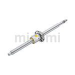
Ball Splines Round Flanged
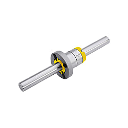
Brand :
MISUMI
Caution
Product Description
Product Overview of Spline Shaft
1. Spline Shaft rolls along the spherical groove using the steel ball inside the spline nut, allowing even a single-axis mechanism to perform linear motion while keeping the nut undeviated in the rotation direction.
2. Compared to the combination of guide shaft and linear bushing, Spline Shaft enables linear motion with high sensitivity and high precision, and can withstand higher loads.
3. Spline Shaft can safely transmit torque even under cantilever load and deliver high durability.
2. Compared to the combination of guide shaft and linear bushing, Spline Shaft enables linear motion with high sensitivity and high precision, and can withstand higher loads.
3. Spline Shaft can safely transmit torque even under cantilever load and deliver high durability.
Product Features of Spline Shaft
1. Spline Shaft Shipping within 5 days after placing an order.
2. Drawing-based machining is no longer required, saving the time for design.
3. Spline Shaft length can be specified in 1mm increments.
4. Various alterations are available to meet different usage scenarios.
5. This product of Spline Shaft has a lower price compared to the MISUMI standard products (produced in Japan) and better performance compared to generic products on the market.
■We have professional testing equipment for guaranteed quality of Spline Shaft
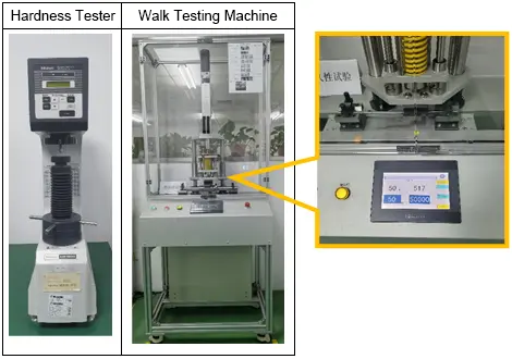
■For this product of Spline Shaft and Generic Products on the Market, we have conducted a service life comparison using a traveling tester.
→Test conditions of Spline Shaft:
Load: 50kgf
Speed: 40cm/s
Travel distance: 100km
Spline shaft diameter: 8mm
→Test result of Spline Shaft:
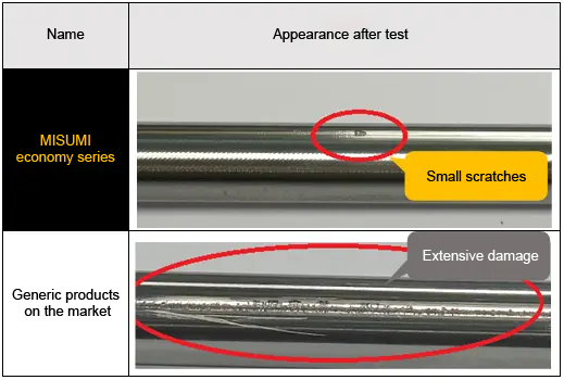
* Generic products of Spline Shaft on the market are similar products randomly purchased by our company from online or offline markets.
* The test data are obtained through testing by our company, which are for reference only.
2. Drawing-based machining is no longer required, saving the time for design.
3. Spline Shaft length can be specified in 1mm increments.
4. Various alterations are available to meet different usage scenarios.
5. This product of Spline Shaft has a lower price compared to the MISUMI standard products (produced in Japan) and better performance compared to generic products on the market.
■We have professional testing equipment for guaranteed quality of Spline Shaft
■For this product of Spline Shaft and Generic Products on the Market, we have conducted a service life comparison using a traveling tester.
→Test conditions of Spline Shaft:
Load: 50kgf
Speed: 40cm/s
Travel distance: 100km
Spline shaft diameter: 8mm
→Test result of Spline Shaft:
* Generic products of Spline Shaft on the market are similar products randomly purchased by our company from online or offline markets.
* The test data are obtained through testing by our company, which are for reference only.
Dimensional Drawing of Spline Shaft
| Accuracy grade | Spline shaft | Nut | ||||||
| Type of Spline Shaft |  Material Material |  Hardness Hardness |  Surface Treatment Surface Treatment | Type | Material | Hardness | Surface Treatment | |
| Grade N | Solid | Equivalent to SUJ2 | 58HRC~ | - | Round flanged | Equivalent to SCR420 | 58HRC~ | - |
Product Drawings of Spline Shaft (Unit: mm)
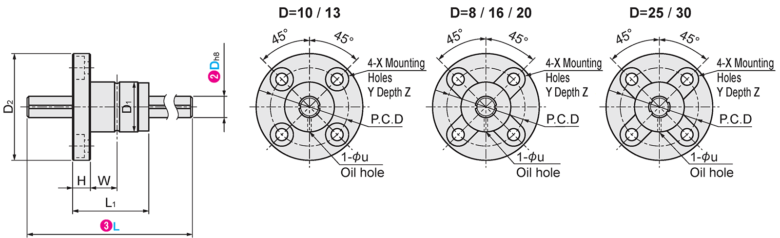
Specification Table of Spline Shaft

 Type of Spline Shaft Type of Spline Shaft |  Dh8 |  L L1mm increments | D1 | D2 | L1 | H | W | P.C.D | X | Y | Z | u | Basic Rated Torque | Basic Load Rating | Static Allowable Moment | ||||
| Dynamic Ct (N·m) | Static C0t (N·m) | Dynamic C (kN) | Static C0 (kN) | M01 (N·m) | M02 (N·m) | ||||||||||||||
| Tolerance | |||||||||||||||||||
| E-BSSM | 8 | 60~300 | 16 | 0 -0.027 | 32 | 27 | 8 | 7.5 | 24 | 3.4 | 6.5 | 4.5 | 1.5 | 3.3 | 6 | 0.8 | 1.4 | 3.5 | 25.2 |
| 10 | 60~400 | 21 | 0 -0.033 | 42 | 33 | 9 | 10.5 | 32 | 4.5 | 8 | 4 | 13.3 | 23.8 | 2.6 | 3.9 | 9.5 | 85.3 | ||
| 13 | 60~400 | 24 | 44 | 36 | 11 | 33 | 4.5 | 19.6 | 36.4 | 3.2 | 5.4 | 15 | 124.6 | ||||||
| 16 | 70~600 | 31 | 0 -0.039 | 51 | 50 | 10 | 18 | 40 | 6 | 2 | 35.7 | 65.1 | 4.3 | 7.7 | 37.1 | 260 | |||
| 20 | 80~700 | 35 | 58 | 56 | 45 | 5.5 | 9.5 | 5.4 | 59.5 | 107.8 | 5.9 | 10.7 | 55.3 | 380 | |||||
| 25 | 90~900 | 42 | 65 | 71 | 13 | 26.5 | 52 | 8 | 3 | 135.1 | 243.6 | 10 | 15 | 103.5 | 685.9 | ||||
| 30 | 100~900 | 47 | 75 | 80 | 30 | 60 | 6.6 | 11 | 190.4 | 343 | 11 | 19.6 | 148.4 | 932.7 | |||||
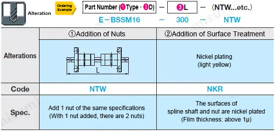
 When Spline Shaft ② is configured, the surface will be light yellow, and there may be a color difference.
Due to the surface treatment process, the following parts are more susceptible to rust.
-Cut section
-Groove part
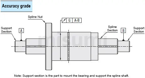
Unit: μm
| Max. Runout of Spline Axis Line | |||||||
| Shaft Dia. D | ~200 | 201~315 | 316~400 | 401~500 | 501~630 | 631~800 | 801~900 |
| 8 | 72 | 133 | 185 | 236 | - | - | - |
| 10 | 59 | 83 | 103 | 123 | 151 | 190 | - |
| 13 | 56 | 71 | 83 | 95 | 112 | 137 | 170 |
| 16 | |||||||
| 20 | |||||||
| 25 | 53 | 58 | 70 | 78 | 88 | 103 | 124 |
| 30 | |||||||
Related Products of Spline Shaft

Precautions of Spline Shaft
■Precautions for Selection and Use of Spline Shaft
1. The relative positions of the grooves of Spline Shaft, the keyways and oil holes of straight nuts, and all the alterations (wrench flat, set screw flat, etc.) in the 3D model are for reference only and may differ from their actualpositions.
2. When re-inserting a nut into the Spline Shaft, be sure to insert it horizontally, otherwise the ball will fall off.
3. As resin parts are used inside the nuts, please use them at temperatures below 80℃.
4. Although the nuts are greased on the inside before leaving the factory, please re-grease them every 2~3 months or every 50km of traveling distance after receipt of the goods, otherwise their use will be impaired.
5. No guarantee is given for the noise level of this product.
6. No guarantee is given that the Spline Shaft or nuts of this product will fall freely.
7. This product is a machined type, so there will be knife patterns and color difference in its appearance. It is normal for the product to have some scratches or color changes. Please feel free to use.
8. The Spline Shaft is quenched, and annealed during machining.
Due to the annealing treatment, the hardness of the machined part + area about 15 mm before and after the part may be reduced (see the following example). And the annealed section is out of the guaranteed range of outerdiameter dimensional tolerance.
Subtract the size of the annealed section when calculating the stroke.
1. The relative positions of the grooves of Spline Shaft, the keyways and oil holes of straight nuts, and all the alterations (wrench flat, set screw flat, etc.) in the 3D model are for reference only and may differ from their actualpositions.
2. When re-inserting a nut into the Spline Shaft, be sure to insert it horizontally, otherwise the ball will fall off.
3. As resin parts are used inside the nuts, please use them at temperatures below 80℃.
4. Although the nuts are greased on the inside before leaving the factory, please re-grease them every 2~3 months or every 50km of traveling distance after receipt of the goods, otherwise their use will be impaired.
5. No guarantee is given for the noise level of this product.
6. No guarantee is given that the Spline Shaft or nuts of this product will fall freely.
7. This product is a machined type, so there will be knife patterns and color difference in its appearance. It is normal for the product to have some scratches or color changes. Please feel free to use.
8. The Spline Shaft is quenched, and annealed during machining.
Due to the annealing treatment, the hardness of the machined part + area about 15 mm before and after the part may be reduced (see the following example). And the annealed section is out of the guaranteed range of outerdiameter dimensional tolerance.
Subtract the size of the annealed section when calculating the stroke.
The parts that may be reduced in hardness due to annealing are:
·Threaded parts
·Stepped parts
·Tapped parts
·Alterations of wrench flats, set screw flat, retaining ring grooves, and tapped holes
·Threaded parts
·Stepped parts
·Tapped parts
·Alterations of wrench flats, set screw flat, retaining ring grooves, and tapped holes
Example Use of Spline Shaft

Brand Introduction of Spline Shaft
Since its establishment in 1963 in Japan, MISUMI Group Inc. has been providing customers with a wide range of high quality parts such as FA factory automation parts, mold parts, electronic parts, tools and consumables in a fast andaccurate manner. We have created a low-cost business model by compiling our own catalogs and establishing a marketing system to sell our products directly, and we continue to develop MISUMI branded products with a high level of quality bydeveloping an annual product plan based on customer feedback and requests. MISUMI established MISUMI Precision Machinery Co., Ltd. in China in June 2003, and then changed its name to MISUMI (China) Precision Machinery Trading Co., Ltd. inJune 2007, with its headquarters in Shanghai. Since the beginning of the stamping die standard parts business, the businesses of FA standard parts, plastic die standard parts and machining tools have been officially started successively,and the rapid development of MISUMI in China has won the full support of customers. China's manufacturing industry has unlimited prospects, which is why China's manufacturing industry market has become one of the most competitiveindustries in the world. Thus was born MISUMI's business philosophy - the key to the future of manufacturing in China is cost competitiveness as well as "quality" and "time".
Dimensional Drawing

Specification Table

 Type Type |  Dh8 |  L L1mm increments | D1 | D2 | L1 | H | W | P.C.D | X | Y | Z | u | Basic Rated Torque | Basic Load Rating | Static Allowable Moment | ||||
| Dynamic Ct (N·m) | Static C0t (N·m) | Dynamic C (kN) | Static C0 (kN) | M01 (N·m) | M02 (N·m) | ||||||||||||||
| Tolerance | |||||||||||||||||||
| E-BSSM | 8 | 60~300 | 16 | 0 -0.027 | 32 | 27 | 8 | 7.5 | 24 | 3.4 | 6.5 | 4.5 | 1.5 | 3.3 | 6 | 0.8 | 1.4 | 3.5 | 25.2 |
| 10 | 60~400 | 21 | 0 -0.033 | 42 | 33 | 9 | 10.5 | 32 | 4.5 | 8 | 4 | 13.3 | 23.8 | 2.6 | 3.9 | 9.5 | 85.3 | ||
| 13 | 60~400 | 24 | 44 | 36 | 11 | 33 | 4.5 | 19.6 | 36.4 | 3.2 | 5.4 | 15 | 124.6 | ||||||
| 16 | 70~600 | 31 | 0 -0.039 | 51 | 50 | 10 | 18 | 40 | 6 | 2 | 35.7 | 65.1 | 4.3 | 7.7 | 37.1 | 260 | |||
| 20 | 80~700 | 35 | 58 | 56 | 45 | 5.5 | 9.5 | 5.4 | 59.5 | 107.8 | 5.9 | 10.7 | 55.3 | 380 | |||||
| 25 | 90~900 | 42 | 65 | 71 | 13 | 26.5 | 52 | 8 | 3 | 135.1 | 243.6 | 10 | 15 | 103.5 | 685.9 | ||||
| 30 | 100~900 | 47 | 75 | 80 | 30 | 60 | 6.6 | 11 | 190.4 | 343 | 11 | 19.6 | 148.4 | 932.7 | |||||
Material Specification
| Accuracy grade | Spline shaft | Nut | ||||||
| Type |  Material Material |  Hardness Hardness |  Surface Treatment Surface Treatment | Type | Material | Hardness | Surface Treatment | |
| Grade N | Solid | Equivalent to SUJ2 | 58HRC~ | - | Round flanged | Equivalent to SCR420 | 58HRC~ | - |
Alterations

 When ② is configured, the surface will be light yellow, and there may be a color difference.
Due to the surface treatment process, the following parts are more susceptible to rust.
-Cut section
-Groove part