Cross Roller Guides
Brand :
MISUMI
Caution
Product Description
Product Overview of Cross Roller Guides
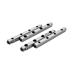
Cross Roller Guides is a finite stroke linear guide that consists of two 90 degree V-groove slide rails loaded with alternating orthogonal cylindrical rollers. Due to its special arrangement, it can withstand torque loads in any direction,making it particularly suitable for linear guidance in situations where high rigidity and flexible movement are required.
Product Features of Cross Roller Guides
Feature of Cross Roller Guides 1: Low rolling friction, most suitable for micro feed. Under light loads, the friction force changes little and the low speed stability performance is good.
Feature of Cross Roller Guides 2: The contact area between the rolling element and the rail surface is large, and the elastic deformation is small. In addition, there are many effective rolling elements, which can achieve high rigidity and high load movement.
Feature of Cross Roller Guides 3: Flexible structural design, easy installation and use, and long service life.
Feature of Cross Roller Guides 4: Low mechanical energy consumption, high accuracy, fast speed, and large load-bearing capacity.
Feature of Cross Roller Guides 2: The contact area between the rolling element and the rail surface is large, and the elastic deformation is small. In addition, there are many effective rolling elements, which can achieve high rigidity and high load movement.
Feature of Cross Roller Guides 3: Flexible structural design, easy installation and use, and long service life.
Feature of Cross Roller Guides 4: Low mechanical energy consumption, high accuracy, fast speed, and large load-bearing capacity.
Dimensional Drawing of Cross Roller Guides
| Type of Cross Roller Guides |  Material Material |  Hardness Hardness | Heat resistant temperature |
E-CRV | Bearing Steel | 60HRC~ | -20℃~110℃ |
E-CRVS | Stainless Steel | 58HRC~ | -20℃~140℃ |

 1 set include 4 rails and 2 retainers
Specifications Overview of Cross Roller Guides

| Series of Cross Roller Guides | Part Number | Stroke (Round Trip) | L | M×P | Roller Quantity | Basic Rated Load | ||
| Type | No. | C (Dynamic) N | Co (Static) N | |||||
| V1 | E-CRV (Bearing Steel) E-CRVS (Stainless Steel) | 1020 | 12 | 20 | 1×10 | 5 | 490 | 345 |
| 1030 | 22 | 30 | 2×10 | 7 | 686 | 483 | ||
| 1040 | 27 | 40 | 3×10 | 10 | 980 | 690 | ||
| 1050 | 32 | 50 | 4×10 | 13 | 1274 | 897 | ||
| 1060 | 37 | 60 | 5×10 | 16 | 1568 | 1104 | ||
| 1070 | 42 | 70 | 6×10 | 19 | 1862 | 1311 | ||
| 1080 | 52 | 80 | 7×10 | 21 | 2058 | 1449 | ||
| V2 | 2030 | 18 | 30 | 1×15 | 5 | 880 | 635 | |
| 2045 | 24 | 45 | 2×15 | 8 | 1408 | 1016 | ||
| 2060 | 30 | 60 | 3×15 | 11 | 1936 | 1397 | ||
| 2075 | 44 | 75 | 4×15 | 13 | 2288 | 1651 | ||
| 2090 | 50 | 90 | 5×15 | 16 | 2816 | 2032 | ||
| 20105 | 64 | 105 | 6×15 | 18 | 3168 | 2286 | ||
| 20120 | 70 | 120 | 7×15 | 21 | 3696 | 2667 | ||
| 20135 | 84 | 135 | 8×15 | 23 | 4048 | 2921 | ||
| 20150 | 90 | 150 | 9×15 | 26 | 4576 | 3302 | ||
| 20165 | 96 | 165 | 10×15 | 29 | 5104 | 3683 | ||
| 20180 | 102 | 180 | 11×15 | 32 | 5632 | 4064 | ||
| V3 | 3050 | 28 | 50 | 1×25 | 7 | 2541 | 1925 | |
| 3075 | 48 | 75 | 2×25 | 10 | 3630 | 2750 | ||
| 30100 | 58 | 100 | 3×25 | 14 | 5082 | 3850 | ||
| 30125 | 78 | 125 | 4×25 | 17 | 6171 | 4675 | ||
| 30150 | 88 | 150 | 5×25 | 21 | 7623 | 5775 | ||
| 30175 | 108 | 175 | 6×25 | 24 | 8712 | 6600 | ||
| 30200 | 118 | 200 | 7×25 | 28 | 10164 | 7700 | ||
| 30225 | 138 | 225 | 8×25 | 31 | 11253 | 8525 | ||
| 30250 | 148 | 250 | 9×25 | 35 | 12705 | 9625 | ||
| V4 | 4080 | 58 | 80 | 1×40 | 7 | 5348 | 4459 | |
| 40120 | 82 | 120 | 2×40 | 11 | 8404 | 7007 | ||
| 40160 | 106 | 160 | 3×40 | 15 | 11460 | 9555 | ||
| 40200 | 130 | 200 | 4×40 | 19 | 14516 | 12103 | ||
| 40240 | 154 | 240 | 5×40 | 23 | 17572 | 14651 | ||
Usage Method of Cross Roller Guides

■Installation Procedure of Cross Roller Guides
①Secure Cross Roller Guides A, B and C to the positioning stage and the table with bolts, and slightly tighten the slide rail D. (Figure 1)
②Remove the end stop and insert the cage from the ends. (Figure 2)
③Move the positioning stage side to side to position the cage in the center of the rail.
④Install the dial indicator in the specified position. (Figure 3)
⑤Drive the positioning stage, and tighten the adjusting screws a to e in the range of the cage with a torque wrench or other tool. (Figures 4 to 6)
⑥Before the value of the dial indicator reaches its minimum and does not change, conduct the operation in step 5.
⑦When the value of the dial indicator is at the minimum and does not change,completely tighten the adjusting screws.
⑧Slightly tighten the Cross Roller Guides D before the final fixation.
①Secure Cross Roller Guides A, B and C to the positioning stage and the table with bolts, and slightly tighten the slide rail D. (Figure 1)
②Remove the end stop and insert the cage from the ends. (Figure 2)
③Move the positioning stage side to side to position the cage in the center of the rail.
④Install the dial indicator in the specified position. (Figure 3)
⑤Drive the positioning stage, and tighten the adjusting screws a to e in the range of the cage with a torque wrench or other tool. (Figures 4 to 6)
⑥Before the value of the dial indicator reaches its minimum and does not change, conduct the operation in step 5.
⑦When the value of the dial indicator is at the minimum and does not change,completely tighten the adjusting screws.
⑧Slightly tighten the Cross Roller Guides D before the final fixation.
Example Use of Cross Roller Guides

Cross Roller Guides is an important component of cross roller guide type positioning stages and often used in positioning stage products. The rollers are arranged in two V-groove guide rails in an alternating and orthogonal manner. TheCross Roller Guides along the V-groove and, as they move, act as a guide mechanism to achieve better motion accuracy.
 The left image shows the MISUMI CRU series cross roller positioning stage Click
 here
here
The left image shows the MISUMI CRU series cross roller positioning stage Click here
hereApplication Industries of Cross Roller Guides
| Electronics/Home Appliance of Cross Roller Guides | Automotive of Cross Roller Guides | |
 |  | |
| Smart Phones of Cross Roller Guides | Semiconductor of Cross Roller Guides | |
 |  |
Precautions of Cross Roller Guides
①Please be careful when using the Cross Roller Guides because it has poor impact resistance and will slide abnormally if dropped or subjected to excessive force.
②Please be careful when using the roller retainer unit until it has been properly fixed and securely installed to prevent the roller from falling off.
③The screw on the slide rail end face only plays the role of preventing the retainer from falling off and cannot be used as a limit mechanism. If you need a limit function, please design a dedicated limit mechanism.
④Principles for paired use of the entire set
The accuracy of the slide rails is accurately controlled on a set by set basis, and mixing different sets of slide rails may cause changes in accuracy. Please pay full attention when assembling.
⑤Prevent retainer offset
When used at half stroke or high speed, the retainer may shift due to inertial forces when the slide stops. As a countermeasure against retainer offset, it is recommended to move several times over full stroke during use and set theretainer in the center position of the slide rail.
⑥Please apply lubricating grease according to the actual usage conditions and environment in a timely manner
Usually, the grease filling interval is 6 months or 1000KM. For longer moving distance, 3 months, or when the moving distance exceeds 1000km within the time limit, the 1000km shall prevail. But this is only the grease filling intervalaccording to the moving distance standard. Depending on the operating environment, the grease injection interval must be shortened appropriately when the grease is aging and dirty.
②Please be careful when using the roller retainer unit until it has been properly fixed and securely installed to prevent the roller from falling off.
③The screw on the slide rail end face only plays the role of preventing the retainer from falling off and cannot be used as a limit mechanism. If you need a limit function, please design a dedicated limit mechanism.
④Principles for paired use of the entire set
The accuracy of the slide rails is accurately controlled on a set by set basis, and mixing different sets of slide rails may cause changes in accuracy. Please pay full attention when assembling.
⑤Prevent retainer offset
When used at half stroke or high speed, the retainer may shift due to inertial forces when the slide stops. As a countermeasure against retainer offset, it is recommended to move several times over full stroke during use and set theretainer in the center position of the slide rail.
⑥Please apply lubricating grease according to the actual usage conditions and environment in a timely manner
Usually, the grease filling interval is 6 months or 1000KM. For longer moving distance, 3 months, or when the moving distance exceeds 1000km within the time limit, the 1000km shall prevail. But this is only the grease filling intervalaccording to the moving distance standard. Depending on the operating environment, the grease injection interval must be shortened appropriately when the grease is aging and dirty.
Related Products of Cross Roller Guides


Dimensional Drawing
| Type |  Material Material |  Hardness Hardness | Heat resistant temperature |
E-CRV | Bearing Steel | 60HRC~ | -20℃~110℃ |
E-CRVS | Stainless Steel | 58HRC~ | -20℃~140℃ |

 1 set include 4 rails and 2 retainers
Specification Table

| Series | Part Number | Stroke (Round Trip) | L | M×P | Roller Quantity | Basic Rated Load | ||
| Type | No. | C (Dynamic) N | Co (Static) N | |||||
| V1 | E-CRV (Bearing Steel) E-CRVS (Stainless Steel) | 1020 | 12 | 20 | 1×10 | 5 | 490 | 345 |
| 1030 | 22 | 30 | 2×10 | 7 | 686 | 483 | ||
| 1040 | 27 | 40 | 3×10 | 10 | 980 | 690 | ||
| 1050 | 32 | 50 | 4×10 | 13 | 1274 | 897 | ||
| 1060 | 37 | 60 | 5×10 | 16 | 1568 | 1104 | ||
| 1070 | 42 | 70 | 6×10 | 19 | 1862 | 1311 | ||
| 1080 | 52 | 80 | 7×10 | 21 | 2058 | 1449 | ||
| V2 | 2030 | 18 | 30 | 1×15 | 5 | 880 | 635 | |
| 2045 | 24 | 45 | 2×15 | 8 | 1408 | 1016 | ||
| 2060 | 30 | 60 | 3×15 | 11 | 1936 | 1397 | ||
| 2075 | 44 | 75 | 4×15 | 13 | 2288 | 1651 | ||
| 2090 | 50 | 90 | 5×15 | 16 | 2816 | 2032 | ||
| 20105 | 64 | 105 | 6×15 | 18 | 3168 | 2286 | ||
| 20120 | 70 | 120 | 7×15 | 21 | 3696 | 2667 | ||
| 20135 | 84 | 135 | 8×15 | 23 | 4048 | 2921 | ||
| 20150 | 90 | 150 | 9×15 | 26 | 4576 | 3302 | ||
| 20165 | 96 | 165 | 10×15 | 29 | 5104 | 3683 | ||
| 20180 | 102 | 180 | 11×15 | 32 | 5632 | 4064 | ||
| V3 | 3050 | 28 | 50 | 1×25 | 7 | 2541 | 1925 | |
| 3075 | 48 | 75 | 2×25 | 10 | 3630 | 2750 | ||
| 30100 | 58 | 100 | 3×25 | 14 | 5082 | 3850 | ||
| 30125 | 78 | 125 | 4×25 | 17 | 6171 | 4675 | ||
| 30150 | 88 | 150 | 5×25 | 21 | 7623 | 5775 | ||
| 30175 | 108 | 175 | 6×25 | 24 | 8712 | 6600 | ||
| 30200 | 118 | 200 | 7×25 | 28 | 10164 | 7700 | ||
| 30225 | 138 | 225 | 8×25 | 31 | 11253 | 8525 | ||
| 30250 | 148 | 250 | 9×25 | 35 | 12705 | 9625 | ||
| V4 | 4080 | 58 | 80 | 1×40 | 7 | 5348 | 4459 | |
| 40120 | 82 | 120 | 2×40 | 11 | 8404 | 7007 | ||
| 40160 | 106 | 160 | 3×40 | 15 | 11460 | 9555 | ||
| 40200 | 130 | 200 | 4×40 | 19 | 14516 | 12103 | ||
| 40240 | 154 | 240 | 5×40 | 23 | 17572 | 14651 | ||
■Stroke
As shown in the figure below, the stroke is symmetrical on both sides, and the movement distance is only 1/2 of the stroke.

■Rated Load
The rated load of the cross roller guide is calculated with the table below.
Single axis use
| Load direction |  | ||
| Dynamic rated load (N) |  | ||
| Static rated load (N) |  | ||
Single-axis vertical use
| Load direction |  | ||
| Dynamic rated load (N) |  | ||
| Static rated load (N) |  | ||
Dual-axis parallel use
| Load direction |  | ||
| Dynamic rated load (N) |  | ||
| Static rated load (N) |  | ||
CO1: Basic static rated load of each roller (N)
Z: Number of rolling elements
Selection Calculation
■Rated Life
The life of cross roller guide is calculated with the formula below.

L: Operating Life (km) fT: Temperature coefficient (see Temperature Coefficient Table) C: Dynamic Load Rating (N)
fw: Load coefficient (see Load Coefficient Table) P: Acting load (N)
Life Time

Lh: Life Hours (hr) L: Operating Life (km)
ls: Stroke length (m) n1: Number of round trips per minute (cpm)
Description of relevant coefficients
● Load coefficient (fW)
When calculating the load acting on the cross roller positioning stage, it is necessary to correctly calculate the inertial force or torque load generated by the speed of the movement and its relationship to the change in time, etc., in addition to the weight of the object. However, it is difficult to attain accurate calculations due to potential vibration and impacts caused during reciprocating motion, other than repeat start-stop motion. Therefore, the load coefficients shown in the table can be used to simplify the operating life calculation.
Table: Load Coefficient
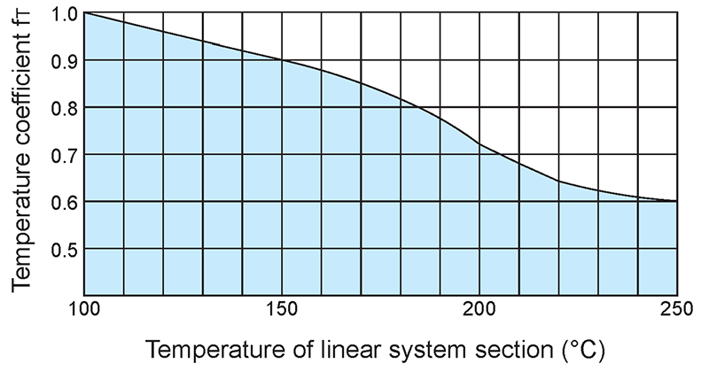
●Temperature coefficient (fT)
If the temperature of the cross roller positioning stage exceeds 100°C, the hardness of the positioning stage and the shaft will decrease, the allowable load will be lower than the load during use at room temperature, and the life will be shortened accordingly. Please use the temperature coefficient to compensate for the rated life.
Please use cross roller positioning stages within the heat-resistance temperature range indicated on each product page.
Figure: Temperature Coefficient
The life of cross roller guide is calculated with the formula below.
L: Operating Life (km) fT: Temperature coefficient (see Temperature Coefficient Table) C: Dynamic Load Rating (N)
fw: Load coefficient (see Load Coefficient Table) P: Acting load (N)
Life Time
Lh: Life Hours (hr) L: Operating Life (km)
ls: Stroke length (m) n1: Number of round trips per minute (cpm)
Description of relevant coefficients
● Load coefficient (fW)
When calculating the load acting on the cross roller positioning stage, it is necessary to correctly calculate the inertial force or torque load generated by the speed of the movement and its relationship to the change in time, etc., in addition to the weight of the object. However, it is difficult to attain accurate calculations due to potential vibration and impacts caused during reciprocating motion, other than repeat start-stop motion. Therefore, the load coefficients shown in the table can be used to simplify the operating life calculation.
Table: Load Coefficient
| Operating Conditions | fw | |
| No external impact vibration | 1.0~1.5 | |
| At low speed | 15m/min or less | |
| No obvious impact vibration | 1.5~2.0 | |
| At medium speed | 60m/min or less | |
| With external impact vibration | 2.0~3.5 | |
| At high speed | 60m/min or more | |
●Temperature coefficient (fT)
If the temperature of the cross roller positioning stage exceeds 100°C, the hardness of the positioning stage and the shaft will decrease, the allowable load will be lower than the load during use at room temperature, and the life will be shortened accordingly. Please use the temperature coefficient to compensate for the rated life.
Please use cross roller positioning stages within the heat-resistance temperature range indicated on each product page.
Figure: Temperature Coefficient
