Timing Pulleys HTD 8M

Caution
Product Description
Timing Pulleys HTD 8M
Timing Pulleys are an economy item, The price is cheaper than the MISUMI standard product.
They offer a wide variety of sizes to choose from.
[Feature]
•Belt Width Used (mm): 20, 25, 30 and 40
•Applicable with Belt Type: 8M
•Pulley Shape: A, B
•Number of Teeth Min./Max.(T): 18 / 60
•Shaft Bore Diameter (mm.): 8, 10, 12, 14 ,15 ,16 and 20
•Shaft Bore Specs.: H (Round Hole), P (Round Hole + Tap), N (New JIS keyway + Tap)
•Material: Aluminum Alloy
•Surface treatment: Clear Anodized
[Application]
Timing pulleys are frequently utilized in systems that incorporate timing belts to regulate and govern the movement of the machinery.
Economy HTD 8M Timing Pulley
- High-quality aluminum
- Range of teeth counts available.
- Various shaft bore options available
- Conforms to JIS and ISO standards
- Enhanced belt life


MISUMI Standard

Cheaper Price

Product Variety

3D CAD Support
Product of Timing Pulley Overview
Usually, flat-belt Timing Pulley and flat belts are widely used in mechanisms design for transmitting rotational power generated by motors.
Driving and transmission are realized through the friction fit between flat-belt pulleys and flat belts.
Product of Timing Pulley Features
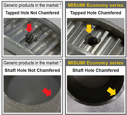
·MISUMI Economy series Timing Pulley is chamfered at the shaft hole and tapped hole for easy installation, reducing assembly time by 27% compared to the timing pulley not chamfered.
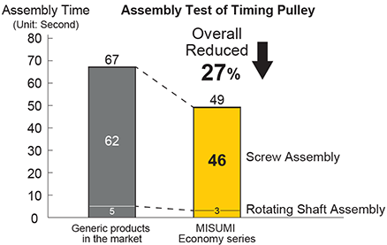
* The values above are averages of test data and may vary individually.
·MISUMI Economy series Timing Pulley, with deburring treatment at the tapped hole, is not easy to wear the timing belt, and the price is cheap while increasing the lifetime of the timing belt.
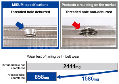 | [Timing Pulley Test conditions] Belt series: 5M Belt width: 15mm Number of teeth of drive side pulley: 20 Number of teeth of driven side pulley: 20 Speed: 3000rpm Tension (N): 110N Test time: 72H |
Dimensional of Timing Pulley Drawing
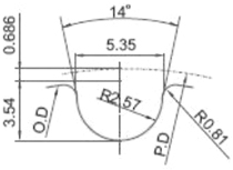
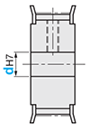
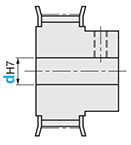
 There may be no surface treatment in the shaft hole.
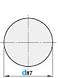 Without threaded holes and fixing screws.
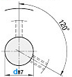 The stop threaded hole of Shape A pulley is located near 120° to avoid interference with the threads.
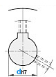 For detailed dimensions of keyway, please click
  Here.The threaded hole of the Shape A pulley is located near 120° to avoid interference with the tooth top.The positions of keyway and tooth are not fixed
(Shaft Bore Specs.: P·N)
| dH7 Shaft Hole ID | 2-M (Coarse Thread) | Single Model of Fixing Screw | Box Model of Fixing Screw |
| 8~12 | M4 | MSSU4-3 | BOX-MSSU4-3 |
| 13 to 17 | M5 | MSSU5-4 | BOX-MSSU5-4 |
| 18 to 20 | M6 | MSSU6-5 | BOX-MSSU6-5 |
Timing Pulley are not provided with fixing screws. You may purchase them separately referring to the recommended fixing screw models.Specifications of Timing Pulley Overview
| Style |  Timing Pulley Material Timing Pulley Material |  Surface Treatment Surface Treatment | ||||
| Belt Width 20mm | Belt Width 25mm | Belt Width 30mm | Belt Width 40mm | Pulley | Flange | |
| A:22 W:27 | A: 28 W: 33 | A: 28 W: 33 | A: 44 W: 49 | Aluminum Alloy | Aluminum Alloy | Clear Anodized |
| H8M200 | H8M250 | H8M250 | H8M400 | |||
The flange is riveted and no fixing screws are included with the economy series products of Timing Pulley.Usage of Timing Pulley Method
| Usage Method Example of Timing Pulley Drawing | Usage Method of Timing Wheel and Timing Belt |
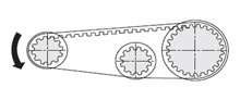 | ①Timing Pulley Driving The driven wheel is driven by the driving wheel for transmission |
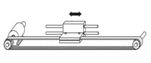 | ②Timing Pulley Linear driving Reciprocating motion is carried out through the self-end timing toothed belt. |
| Usage Method Example of Timing Pulley Drawing | Usage Method of Timing Wheel and Timing Belt |
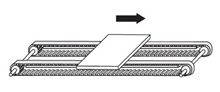 | ③Timing Pulley Conveyance Plates are conveyed by two Timing Pulley toothed belts |
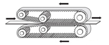 | ④Timing Pulley Traction transmission Workpieces are clamped and transmitted by the belt |
HTD 8M timing pulleys, suitable for MISUMI HTD 8M timing belts.Example of Timing Pulley Use
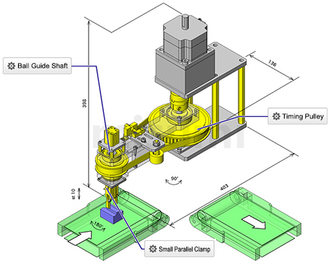
Workpiece Reversal Transfer Mechanism
■ Mechanism function
The workpiece moving on the conveyor belt rotates 90 degrees and then transfers to the next process.
The chuck mechanism rotates 180 degrees and transfers the workpiece without changing the direction of the workpiece relative to the conveying direction.
■Role of the timing pulley
The transmission of the timing pulley and the timing belt changes the placement direction of the workpiece while transferring the workpiece. (Applicable to S specification and GT specification timing pulleys)
For details, please click Workpiece Reversal Transfer Mechanism.
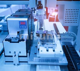
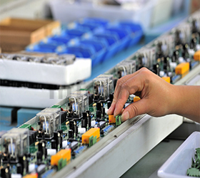
Related of Timing Pulley Industries
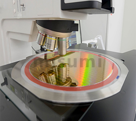
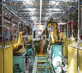
| Semiconductor | Automotive | Smart phone | ||
 |  |  | ||
| Medical | Electronic & Electrical Appliances | Robotics | ||
 |  |  |
Timing Pulley Precautions
Economy series product are not provided with fixing screws, and you may purchase them from MISUMI according to the recommended fixing screw Timing Pulley models.There may be no surface treatment in the shaft hole.The positions of keyway and tooth are not fixed.Related of Timing Pulley Documents
①Data on the selection of timing pulleys and timing toothed belts, tensioning force, etc. (drive).
②Data on the selection of timing pulleys and timing toothed belts, tensioning force, etc. (transmission & conveyance).
③Main causes and countermeasures for the damage, breakage, abnormal noise of timing toothed belts.
④Reference data on the replacement time of timing toothed belts.
⑤Data on dimensional tolerance of timing pulleys and timing idlers.
Related of Timing Pulley Products
| Idlers HTD 3M | Idlers HTD 5M | Timing Belts HTD 8M | ||
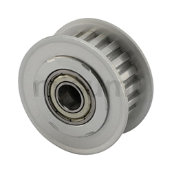 | 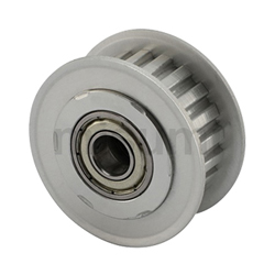 | 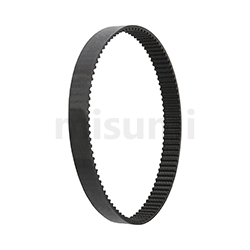 | ||
| Typical Timing Pulley model: C-AHTF20H3M060 | Typical Timing Pulley model: C-AHTF20H5M090 | Typical Timing Pulley model: C-HTBN1000H8M-200 | ||
| Advantages: short delivery time, multiple types | Advantages: Short delivery time, multiple types | Advantages: short delivery time, multiple types |


 There may be no surface treatment in the shaft hole.
 Without threaded holes and fixing screws.
 The set screw of Shape A pulley is located near 120° to avoid interference with the threads.
 For detailed dimensions of keyway, please click
  Here.The threaded hole of the Shape A pulley is located near 120° to avoid interference with the tooth top.The positions of keyway and tooth are not fixed
(Shaft Bore Specs.: P·N)
| dH7 Shaft Hole ID | 2-M (Coarse Thread) | Single Model of Fixing Screw | Box Model of Fixing Screw |
| 8~12 | M4 | MSSU4-3 | BOX-MSSU4-3 |
| 13 to 17 | M5 | MSSU5-4 | BOX-MSSU5-4 |
| 18 to 20 | M6 | MSSU6-5 | BOX-MSSU6-5 |
Timing pulleys are not provided with fixing screws. You may purchase them separately referring to the recommended fixing screw models.| Style |  Material Material |  Surface Treatment Surface Treatment | ||||
| Belt Width 20mm | Belt Width 25mm | Belt Width 30mm | Belt Width 40mm | Pulley | Flange | |
| A:22 W:27 | A:28 W:33 | A:28 W:33 | A:44 W:49 | Aluminum Alloy | Aluminum Alloy | Clear Anodized |
| H8M200 | H8M250 | H8M250 | H8M400 | |||
■ Dimension Specification Table
| Style | Pulley Shape | Shaft Bore Specs. (1mm increments) | P.D. | O.D. | F | E | |||
| Number of Teeth | Type Nominal Width | H Round Hole | P Round Hole + Tap | N Keyway Hole + Tap | |||||
| 18 | H8M200 *A:22 *W:27 H8M250 *A:28 *W:33 H8M300 *A:33 *W:38 H8M400 *A:44 *W:49 | A | 12~28 | 12~26 | 12~26 | 45.84 | 44.47 | 51 | 36 |
| 19 | 12~32 | 12~28 | 12~28 | 48.38 | 47.01 | 55 | 39 | ||
| 20 | 12~32 | 12~30 | 12~30 | 50.93 | 49.56 | 57 | 41 | ||
| 21 | 12~37 | 12~32 | 12~32 | 53.47 | 52.10 | 60 | 46 | ||
| 22 | 12~37 | 12~34 | 12~34 | 56.02 | 54.65 | 60 | 46 | ||
| 24 | 12~42 | 12~40 | 12~40 | 61.12 | 59.75 | 67 | 50 | ||
| 25 | 12~48 | 12~40 | 12~40 | 63.66 | 62.29 | 69 | 54 | ||
| 26 | 14~50 | 14~45 | 14~45 | 66.21 | 64.84 | 75 | 55 | ||
| 28 | 14~52 | 14~48 | 14~48 | 71.30 | 69.93 | 78 | 58 | ||
| 30 | 14~59 | 14~50 | 14~50 | 76.39 | 75.02 | 86 | 66 | ||
| 32 | 14~59 | 14~55 | 14~50 | 81.49 | 80.12 | 86 | 66 | ||
| 34 | 16~67 | 16~60 | 16~50 | 86.58 | 85.21 | 94 | 74 | ||
| 36 | 16~72 | 16~65 | 16~50 | 91.67 | 90.30 | 99 | 78 | ||
| 38 | 16~76 | 16~65 | 16~50 | 96.77 | 95.40 | 105 | 84 | ||
| 40 | 20~80 | 20~65 | 20~50 | 101.86 | 100.49 | 112 | 90 | ||
| 44 | 20~80 | 20~65 | 20~50 | 112.05 | 110.68 | 119 | 100 | ||
| 48 | 20~80 | 20~65 | 20~50 | 122.23 | 120.86 | 131 | 111 | ||
| 50 | 20~80 | 20~65 | 20~50 | 127.32 | 125.95 | 135 | 115 | ||
| 60 | 20~80 | 20~65 | 20~50 | 152.79 | 151.42 | 160 | 140 | ||
| Style | Pulley Shape | Shaft Bore Specs. (1mm increments) | P.D. | O.D. | F | E | |||
| Number of Teeth | Type Nominal Width | H Round Hole | P Round Hole + Tap | N Keyway Hole + Tap | |||||
| 18 | H8M200 *A:22 *W:27 H8M250 *A:28 *W:33 H8M300 *A:33 *W:38 H8M400 *A:44 *W:49 | B | 12~28 | 12~26 | 12~26 | 45.84 | 44.47 | 51 | 36 |
| 19 | 12~32 | 12~28 | 12~28 | 48.38 | 47.01 | 55 | 39 | ||
| 20 | 12~32 | 12~30 | 12~30 | 50.93 | 49.56 | 57 | 41 | ||
| 21 | 12~37 | 12~32 | 12~32 | 53.47 | 52.10 | 60 | 46 | ||
| 22 | 12~37 | 12~34 | 12~34 | 56.02 | 54.65 | 60 | 46 | ||
| 24 | 12~42 | 12~40 | 12~40 | 61.12 | 59.75 | 67 | 50 | ||
| 25 | 12~48 | 12~40 | 12~40 | 63.66 | 62.29 | 69 | 54 | ||
| 26 | 14~50 | 14~45 | 14~45 | 66.21 | 64.84 | 75 | 55 | ||
| 28 | 14~52 | 14~48 | 14~48 | 71.30 | 69.93 | 78 | 58 | ||
| 30 | 14~59 | 14~50 | 14~50 | 76.39 | 75.02 | 86 | 66 | ||
| 32 | 14~59 | 14~55 | 14~50 | 81.49 | 80.12 | 86 | 66 | ||
| 34 | 16~67 | 16~60 | 16~50 | 86.58 | 85.21 | 94 | 74 | ||
| 36 | 16~72 | 16~65 | 16~50 | 91.67 | 90.30 | 99 | 78 | ||
| 38 | 16~76 | 16~65 | 16~50 | 96.77 | 95.40 | 105 | 84 | ||
| 40 | 20~80 | 20~65 | 20~50 | 101.86 | 100.49 | 112 | 90 | ||
| 44 | 20~80 | 20~65 | 20~50 | 112.05 | 110.68 | 119 | 100 | ||
| 48 | 20~80 | 20~65 | 20~50 | 122.23 | 120.86 | 131 | 111 | ||
| 50 | 20~80 | 20~65 | 20~50 | 127.32 | 125.95 | 135 | 115 | ||
| 60 | 20~80 | 20~65 | 20~50 | 152.79 | 151.42 | 160 | 140 | ||