Linear Shafts Both Ends Tapped

Brand :
MISUMI
Caution
Product Description

Product Overview
Linear guide shafts are high-precision shaft products that can be used with linear bushings and other bushing-type products. They not only offer excellent wear resistance, but also provide a variety of additional machining options.
Dimensional Drawing

Specifications Overview
| Type |  Material Material |  Hardness Hardness |  Surface Treatment Surface Treatment | |
| Standard | ||||
| D tolerance g7 | D tolerance f8 | |||
| E-SFJW | - | S45C or GCr15 | High-frequency quenching Effective hardened layer depth>>See (PDF) S45C or GCr15 55HRC~ SUS440C or high-hardness corrosion-resistant steel 53HRC or more | - |
| E-SSFJW | - | SUS440C or high-hardness corrosion-resistant steel | ||
| E-PSFJW | - | S45C or GCr15 | Hard Chrome Plating Plating Hardness HV750~ Plating Thickness 3µ or more | |
| E-PSSFJW | - | SUS440C or high-hardness corrosion-resistant steel | ||
| - | E-PSFGW | S45C Equivalent | - | Hard Chrome Plating Plating Hardness HV750~ Plating Thickness 10µ or more |
 The total length L must satisfy M × 2+N × 2 ≤ L. When M × 2.5+4+N × 2.5+4 ≥ L, the thread bottom hole may penetrate through. The shaft end processing section (effective thread length + approx. 10 mm) may experience reduced hardness due to the annealing effect of the processing. If there are requirements for rust prevention, give priority to products with hard chrome plated surface treatment. For rust prevention methods, please click
  here If used with linear bushings, please select products with high-frequency quenching.
Alterations
| Alterations | Code | Spec. | ||
 | LKC | Change L dimension tolerance Specification Method LKC Applicable Conditions The maximum L dimension for precision type is 200 When using LKC, the L dimension can be specified in 0.1 mm increments L<200 →L±0.03200 ≤ L<500 →L±0.05 L ≥ 500 →L±0.1 | ||
 | SC | 1 additional wrench slot machining Specification method SC5 SC = specified unit 1 mm SC+ℓ1 < L SC = 0 or SC ≥ 1Applicable conditions D = 6 or above applicable  Cannot be used together with WSC Cannot be used together with WSC | ||
M Side | WSC | |||
 | FC | |||
 | WFC | |||
 | WRC | |||
Precision Reference
■D Tolerance
■ Tolerance of L size (Y size)
| D Tolerance | ||
| D | g7 | f8 |
| 4 | -0.004 -0.016 | - |
| 5 | ||
| 6 | -0.010 -0.028 | |
| 8 | -0.005 -0.020 | -0.013 -0.035 |
| 10 | ||
| 12 | -0.006 -0.024 | -0.016 -0.043 |
| 13 | ||
| 15 | ||
| 16 | ||
| 20 | -0.007 -0.028 | -0.020 -0.053 |
| 25 | ||
| 30 | ||
| 35 | -0.009 -0.034 | -0.025 -0.064 |
| 40 | ||
| 50 | ||
■ Tolerance of L size (Y size)
| Dimensions (Greater Than) | Dimensions (To) | Shaft tolerance g7 |
| 2 | 6 | ±0.1 |
| 6 | 30 | ±0.2 |
| 30 | 120 | ±0.3 |
| 120 | 400 | ±0.5 |
| 400 | 1000 | ±0.8 |
| 1000 | 1500 | ±1.2 |
Specification Table
| Part Number |  L can be specified down to 1 mm increments L can be specified down to 1 mm increments |  M (Coarse Thread) M (Coarse Thread)  N (Coarse Thread) Selection N (Coarse Thread) Selection | |||||||||||||
 Type Type |  D D | Standard | |||||||||||||
| Standard (D Tolerance g7) E-SFJW E-SSFJW E-PSFJW E-PSSFJW (D Tolerance f8) E-PSFGW | 4 | 20 to 300 | 2 | ||||||||||||
| 5 | 20 to 400 | 2.6 | 3 | ||||||||||||
| 6 | 20 to 800 | 3 | |||||||||||||
| 8 | 20 to 1000 | 3 | 4 | 5 | |||||||||||
| 10 | 20 to 1000 | 3 | 4 | 5 | 6 | ||||||||||
| 12 | 20 to 1200 | 4 | 5 | 6 | 8 | ||||||||||
| 13 | 25 to 1200 | 4 | 5 | 6 | 8 | ||||||||||
| 15 | 25 to 1200 | 4 | 5 | 6 | 8 | 10 | |||||||||
| 16 | 30 to 1200 | 4 | 5 | 6 | 8 | 10 | |||||||||
| 20 | 30 to 1200 | 4 | 5 | 6 | 8 | 10 | 12 | ||||||||
| 25 | 35 to 1200 | 4 | 5 | 6 | 8 | 10 | 12 | 16 | |||||||
| 30 | 35 to 1500 | 6 | 8 | 10 | 12 | 16 | 20 | ||||||||
| 35 | 35 to 1500 | 8 | 10 | 12 | 16 | 20 | 24 | ||||||||
| 40 | 50 to 1500 | 10 | 12 | 16 | 20 | 24 | 30 | ||||||||
| 50 | 65 to 1500 | 12 | 16 | 20 | 24 | 30 | |||||||||
Outer diameters 35, 40, 50 are only applicable to E-PSFJW Outer diameters 4, 5 are not applicable to E-PSFGW Total length L requires M×2+N×2≤L. When M×2.5+4+N×2.5+4≥L, tap pilot holes may go through. The hardness of shaft end machined part (effective thread length + approx. 10mm) may be reduced due to the annealing effect of machining. If there are requirements for rust prevention, please give priority to the hard-chrome plated products. For anti-rust method, click here If there are requirements for abrasion resistance, please select high-frequency quenched products.Product Features
Feature 1: Has high-precision dimensional tolerances and is widely used in various precision equipment.
Feature 2: Uses bearing steel (S45C or GCr15) with excellent wear resistance and SUS440C or equivalent high-hardness corrosion-resistant steel, which are high-frequency quenched to enhance wear resistance while maintaining original toughness.
Feature 3: Various additional processing options are available to meet different usage environments.
Feature 4: Usually used in combination with linear bushings products, it provides excellent linear guidance. Compared to general shaft and bushing structures, even during high-speed reciprocating motion, there is minimal wear.
Feature 5: Optional hard chrome plating provides excellent rust resistance, and the coating hardness reaches HV750. It will not be easily worn when used with high-hardness workpieces.
Precautions
 | (2) Decreased hardness in the machined area After quenching the base material, machining may cause some areas to lose hardness due to annealing: - All external threads - All steps - Internal threads: When M ≥ D/2, double-hole internal thread type, hard chrome plated products made of SUS440C or high-hardness corrosion-resistant steel - Additional processing for wrench slot (SC-WSC-SX) - Additional processing for flat surface (FC-WFC) - Additional processing for V-groove (VC-WVC) - Except for full-length hardened type. |
Only the shaded area of section D is hard chrome plated.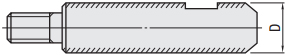 | (3) Coating for Surface Treatment After surface treatment of the base material, processing is performed. The following areas are not plated: - Grooved section -External thread section -Internal thread section -Wrench slot, V-groove, flat surface, cut surface -The inside of the pipe-type guide shaft may rust if hard chrome plating is not applied. |
Example of Use
Standard Linear Motion Mechanism
Example Image
Example Image

Functions of Standard Linear Motion Mechanisms
(1) Using two guide shafts in parallel effectively prevents workpiece rotation
(2) Improves the accuracy and load capacity of linear motion.
(3) High-speed reciprocating motion can be achieved through the combination of guide shafts and linear bushings.
(4) Lower running resistance, resulting in less wear on the corresponding workpiece.
Actual Product Image

Functions of Key Components in the Mechanism
Application Industries


Related Products
| Linear bushings Standard type Straight type | Shaft support Bracket type | Shaft Collar Slit | ||
 |  | 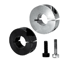 | ||
| Typical model: LMU8 | Typical model: STHRB8 | Typical model: SCS8-10 |
Related Documents
Anti-rust performance of metal materials and surface treatment Click  here
here
here