Sprockets Nominal No.16B

Brand :
MISUMI
Caution
Product Description

Product Overview of Sprockets
■ Sprockets or spoked gear that engages with a roller chain to transfer motion or power.
Application of Sprockets: It is widely used in mechanical transmission in chemical industry, textile machinery, food processing, instrumentation,and petroleum
■ Only Sprockets and chains of the same specifications can be used in combination.
This series is ISO 16B Sprockets, and can be used in combination with MISUMI 40B series chain.
■ Do not use it with ISO/ANSI 16A series chain, which may cause the chain Sprockets mechanism to fail to function properly!
Please note that some yellow anti-rust oil may be adhered on the surface of the delivered Sprockets, which does not affect the use and can be cleaned by yourself. ■ Due to process reasons, it is impossible to guarantee the coincidence of the tooth tops of multiple Sprockets. If you need to use the tooth tops in an overlapping manner, please contact us.
Product Features of Sprockets
■ Compared with gear drive and belt drive, Sprockets chain drive has the following characteristics:
1. Sprockets, Multi-tooth load-bearing, safe and reliable;
2. Sprockets, Flexible transmission, absorbing shock and vibration;
3. Sprockets, Large center distance range, low manufacturing and installation accuracy requirements;
4. Sprockets, Compared with belt transmission, the transmission ratio is more accurate and the transmission efficiency is higher. It is suitable for the harsh environment of high temperature, dust and humidity.
■ Sprockets, chain selection
Misumi’s Sprockets and chain product selection supports the principle of “Nominal Numbering”

Dimensional Drawing of Sprockets
Product Drawings (Unit: mm)

■ Technical information of Chain Transmission Mechanism design →Click here
■ A single package label may not match the ordered model. It is a factory-managed model. Please note that the outer package label shall prevail!

 Material Material |  Surface Treatment Surface Treatment |  Attachments Attachments |
| Equivalent to S45C (Teeth Tip: Induction hardening) | - | Fixing Screw (Only Shaft Hole Specifications N) |
■ A single package label may not match the ordered model. It is a factory-managed model. Please note that the outer package label shall prevail!
Specifications Overview of Sprockets
| Nominal Model | Hub type | Number of Teeth | Shaft Hole Specifications | Shaft Hole Diameter (D) | Dp | D0 | H | L | ℓ | ||||||||||
| S Specifications | N Specifications (H7) | ||||||||||||||||||
| 16 | B | 11 | S N | 16 | 25 | 30 | 90.14 | 101.7 | 61 | 40 | 12 | ||||||||
| 12 | 16 | 25 | 30 | 35 | 38 | 98.14 | 109.7 | 69 | |||||||||||
| 13 | 16 | 35 | 38 | 45 | 48 | 106.12 | 117.7 | 78 | |||||||||||
| 14 | 16 | 50 | 114.15 | 125.7 | 84 | ||||||||||||||
| 15 | 16 | 40 | 45 | 122.17 | 133.7 | 92 | |||||||||||||
| 16 | 20 | 25 | 45 | 130.20 | 141.8 | 100 | 45 | 14 | |||||||||||
| 18 | 20 | 35 | 146.28 | 157.8 | |||||||||||||||
| 19 | 20 | 38 | 45 | 48 | 154.33 | 165.9 | |||||||||||||
| 22 | 20 | 35 | 40 | 45 | 48 | 178.48 | 190.1 | 110 | 50 | 16 | |||||||||
| 24 | 20 | 35 | 50 | 194.59 | 206.2 | ||||||||||||||
| 25 | 20 | 30 | 40 | 42 | 48 | 202.66 | 214.2 | ||||||||||||
■ Shaft Hole Machining Size Table
| Shaft Hole Diameter D | Keyway b2×t2 | Fixing Screw M |
| 25~30 | 8×3.3 | 8 |
| 32~38 | 10×3.3 | 8 |
| 40·42 | 12×3.3 | 8 |
| 45·50 | 14×3.8 | 10 |
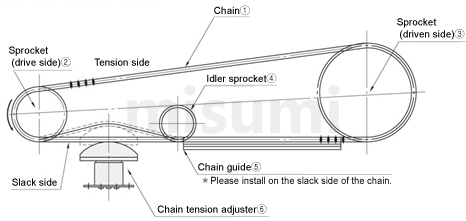
Example Use of Sprockets


Precautions of Sprockets
■ Sprockets maintenance
1. Sprockets tightness should be suitable. If it is too tight, it will increase power consumption, and bearing is easy to wear; if it is too loose, the Sprockets is easy to runout and fall off the chain.
The degree of tightness of the Sprockets is: if lifted up or pressed down from the middle of the Sprockets, the center distance between the two Sprockets is about 2%-3%.
2. The Sprockets shall be installed on shaft without swing and skew.
The end faces of the two Sprockets in the same transmission assembly should be in the same plane. When the center distance of the Sprockets is less than 0.5 m, the deviation can be 1 mm;
When the center distance of the Sprockets is more than 0.5 m, the deviation can be 2 mm. But there shall be no friction on Sprockets tooth side. Integral offset.
If the offset is too large, chain is prone to fall off and wear is likely to accelerate. When replacing the Sprockets, you must pay attention to check and adjust the offset
3. After the Sprockets is severely worn, the new Sprockets and the new chain should be replaced at the same time to ensure good meshing.
You cannot replace new Sprockets separately. Otherwise, it will cause bad engagement and accelerate the wear of new Sprockets.
If the tooth surface of the Sprockets is worn to a certain degree, it should be turned over in time (the Sprockets used with adjustable surface) to extend the life time.
4. If the new Sprockets is too long or elongated after use, and difficult to adjust, the links can be removed by the case, but the number of the links must be even.
The link should pass through the back of the Sprockets with the lock piece being inserted outside, and the opening of the lock piece should be in the opposite direction of the turning.
5. Lubricating oil should be timely filled when Sprockets are working. Lubricating oil must enter the matching clearance between the roller and the inner sleeve to improve working conditions and reduce wear.
6. The old Sprockets cannot be mixed with some of the new Sprockets, and should be replaced as a complete set, otherwise it is easy to produce impact in the transmission. Separate replacement of Sprockets will increase wear.
Dimensional Drawing
Product Drawings (Unit: mm)

■ Technical information of Chain Transmission Mechanism design →Click here
■ A single package label may not match the ordered model. It is a factory-managed model. Please note that the outer package label shall prevail!

 Material Material |  Surface Treatment Surface Treatment |  Attachments Attachments |
| Equivalent to S45C (Teeth Tip: Induction hardening) | - | Fixing Screw (Only Shaft Hole Specifications N) |
■ A single package label may not match the ordered model. It is a factory-managed model. Please note that the outer package label shall prevail!
Specification Table
| Nominal Model | Hub type | Number of Teeth | Shaft Hole Specifications | Shaft Hole Diameter (D) | Dp | D0 | H | L | ℓ | ||||||||||
| S Specifications | N Specifications (H7) | ||||||||||||||||||
| 16 | B | 11 | S N | 16 | 25 | 30 | 90.14 | 101.7 | 61 | 40 | 12 | ||||||||
| 12 | 16 | 25 | 30 | 35 | 38 | 98.14 | 109.7 | 69 | |||||||||||
| 13 | 16 | 35 | 38 | 45 | 48 | 106.12 | 117.7 | 78 | |||||||||||
| 14 | 16 | 50 | 114.15 | 125.7 | 84 | ||||||||||||||
| 15 | 16 | 40 | 45 | 122.17 | 133.7 | 92 | |||||||||||||
| 16 | 20 | 25 | 45 | 130.20 | 141.8 | 100 | 45 | 14 | |||||||||||
| 18 | 20 | 35 | 146.28 | 157.8 | |||||||||||||||
| 19 | 20 | 38 | 45 | 48 | 154.33 | 165.9 | |||||||||||||
| 22 | 20 | 35 | 40 | 45 | 48 | 178.48 | 190.1 | 110 | 50 | 16 | |||||||||
| 24 | 20 | 35 | 50 | 194.59 | 206.2 | ||||||||||||||
| 25 | 20 | 30 | 40 | 42 | 48 | 202.66 | 214.2 | ||||||||||||
■ Shaft Hole Machining Size Table
| Shaft Hole Diameter D | Keyway b2×t2 | Fixing Screw M |
| 25~30 | 8×3.3 | 6 |
| 32~38 | 10×3.3 | 8 |
| 40·42 | 12×3.3 | 10 |
| 45·50 | 14×3.8 | 12 |