(!)NOTE : Windows 7 users won’t be able to use some latest features of eCatalog/WOS since Microsoft is ending support for Windows 7 on 14 Jan, 2020. Please upgrade your system for uninterrupted services.
- Scheduled Maintenance Notice: This site will be unavailable due to scheduled maintenance from 6:30 28/7/2024 to 4:30 (IST) 29/7/2024. We apologize for the inconvenience.
- Notice of End of Sales for Economy Series Pneumatic Equipment Category. More information.
Sprockets Nominal No.80

- Volume Discount
You can add up to 6 items per a category to the compare list.
Brand :
MiSUMi Economy
Part Number :

Copy Part Number URL to Clipboard
The part number URL has been copied into your clipboard.-
- Starting From :
- 4,012₹/Unit

-
- Order Qty :
-
-
- Total Price :
- ---
-
- Days to ship :
- ---
Select part number to Order Now/ Add to Cart
Actual Product

Usage Method
Specification Table
Symbol * indicates that there is a notch on the outer diameter of the hub.
■ A single package label may not match the ordered model. It is a factory-managed model. Please note that the outer package label shall prevail!
■ Shaft Hole Machining Size Table

Product Overview
■ Sprocket is a solid or spoked gear that engages with a roller chain to transfer motion or power.
Application of sprocket: It is widely used in mechanical transmission in chemical industry, textile machinery, food processing, instrumentation,and petroleum
■ Only sprockets and chains of the same specifications can be used in combination.
This series is ISO 16A/ANSI 80 sprocket, and can be used in combination with MISUMI 80 series chain.
■ Do not use it with ISO/ANSI 16B series chain, which may cause the chain sprocket mechanism to fail to function properly!
■ Due to process reasons, it is impossible to guarantee the coincidence of the tooth tops of multiple sprockets. If you need to use the tooth tops in an overlapping manner, please contact us.
Product Feature
■ Compared with gear drive and belt drive, sprocket chain drive has the following characteristics:
1. Multi-tooth load-bearing, safe and reliable;
2. Flexible transmission, absorbing shock and vibration;
3. Large center distance range, low manufacturing and installation accuracy requirements;
4. Compared with belt transmission, the transmission ratio is more accurate and the transmission efficiency is higher. It is suitable for the harsh environment of high temperature, dust and humidity.
■ Sprocket, chain selection
Misumi’s sprocket and chain product selection supports the principle of “Nominal Numbering”

Dimensional Drawing
Product Drawings (Unit: mm)
This series is 16A Japanese Standard sprocket, and can not be used in combination with Chinese Standard 16B series sprocket.
■ A single package label may not match the ordered model. It is a factory-managed model. Please note that the outer package label shall prevail!
■ The engraving of sprocket body may be different from the ordered model, please check the engraving number.
 * Fixing Screw of Symbol * is M6.
** Symbol indicates that there is a notch on the outer diameter of the hub.
■ A single package label may not match the ordered model. It is a factory-managed model. Please note that the outer package label shall prevail!

| Type |  Material Material |  Accessories Accessories |
| C-SPA80B | Equivalent to S45C (Induction Hardened Teeth Tip) | Fixing Screw (Only Shaft Hole Specifications N) |
■ A single package label may not match the ordered model. It is a factory-managed model. Please note that the outer package label shall prevail!
■ The engraving of sprocket body may be different from the ordered model, please check the engraving number.
 * Fixing Screw of Symbol * is M6.** Symbol indicates that there is a notch on the outer diameter of the hub.
■ A single package label may not match the ordered model. It is a factory-managed model. Please note that the outer package label shall prevail!
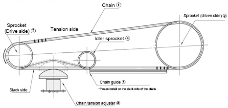
Usage Method


Example of Use


Precautions
■ Sprocket maintenance
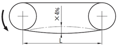
1. Sprocket tightness should be suitable. If it is too tight, it will increase power consumption, and bearing is easy to wear; if it is too loose, the sprocket is easy to runout and fall off the chain.
The degree of tightness of the sprocket is: if lifted up or pressed down from the middle of the sprocket, the center distance between the two sprocket is about 2%-3%.
2. The sprocket shall be installed on shaft without swing and skew.
The end faces of the two sprockets in the same transmission assembly should be in the same plane. When the center distance of the sprocket is less than 0.5 meters, the deviation can be 1 mm.
When the center distance of the sprocket is more than 0.5 meters, the deviation can be 2 mm. But there shall be no friction on sprocket tooth side. Integral offset.
If the offset is too large, chain is prone to fall off and wear is likely to accelerate. When replacing the sprocket, you must pay attention to check and adjust the offset
3. After the sprocket is severely worn, the new sprocket and the new chain should be replaced at the same time to ensure good meshing.
You cannot replace new sprockets separately. Otherwise, it will cause bad engagement and accelerate the wear of new sprockets.
If the tooth surface of the sprocket is worn to a certain degree, it should be turned over in time (the sprocket used with adjustable surface) to extend the life time.
4. If the new sprocket is too long or elongated after use, and difficult to adjust, the links can be removed by the case, but the number of the links must be even.
The link should pass through the back of the sprocket with the lock piece being inserted outside, and the opening of the lock piece should be in the opposite direction of the turning.
5. Lubricating oil should be timely filled when sprockets are working. Lubricating oil must enter the matching clearance between the roller and the inner sleeve to improve working conditions and reduce wear.
6. The old sprocket cannot be mixed with some of the new sprocket, and should be replaced as a complete set, otherwise it is easy to produce impact in the transmission. Separate replacement of sprockets will increase wear.
Specification Table
Part Number ( Type· Type· No. of Teeth) No. of Teeth) | - |  Specifications Specifications | - |  Shaft Hole Diameter Shaft Hole Diameter | |
| Sprocket | C-SPA80B15 | - | N | - | 40 |
| Part Number | Shaft Hole Specifications | Shaft Hole Diameter (D) | Dp | D0 | H | L | ℓ | |||||||
| Type | Nominal model | Hub type | Number of Teeth | S Specifications | N Specifications (H7) | |||||||||
| C-SPA | 80 | B | 12 | S N | 15 | 40 | 98.14 | 110 | 67 | 40 | 12 | |||
| 14 | 16 | 25 | 114.15 | 127 | 77 | |||||||||
| 15 | 20 | 50 | 122.17 | 135 | 93 | |||||||||
| 16 | 20 | 25 | 130.2 | 143 | ||||||||||
| 17 | 20 | 50 | 138.23 | 151 | ||||||||||
| 20 | 20 | 35 | 162.37 | 176 | ||||||||||
■ A single package label may not match the ordered model. It is a factory-managed model. Please note that the outer package label shall prevail!
■ Shaft Hole Machining Size Table
| Shaft Hole Diameter D | Keyway b2×t2 | Fixing Screw M |
| 25~30 | 8×3.3 | 8 |
| 32~38 | 10×3.3 | 8 |
| 40·42 | 12×3.3 | 8 |
| 45·50 | 14×3.8 | 10 |
Part Number
- Incomplete part number.
Please use left hand selections to complete a part number.
Loading...
Basic Information
| Sprocket Shape | Shape B | Nominal | 80 | Number of Teeth(T) | 12 |
|---|---|---|---|---|---|
| Shaft Bore Dia. D (or d)(mm) | 15 | Number of Strands | 1 | Material | S45C |
| Chain Type | RS | Type | Pilot Bore Type | Shaft Type | Standard Pilot Bore |
| Surface Treatment | Not Provided | Bore Specification | S (Through Hole) |
Please check the type/dimensions/specifications of the part C-SPA80B12-S-15 in the Sprockets Nominal No.80 series.
- The specifications and dimensions of some parts may not be fully covered. For exact details, refer to manufacturer catalogs .
Frequently asked question (FAQ)
- Question: I bought MISUMI chains, but why can't I use them on my original sprocket?
- Answer: Please confirm the specifications of the original sprocket and chain. Specification series number may not match. In addition, there are two specifications: A series and B series in China. The two specifications of sprocket chain are not universal.
- Question: Does the sprocket need routine maintenance after installation and use?
- Answer: The chain needs regular maintenance after installation and use. These include daily lubricant application, confirmation of chain slack. After the sprocket is severely worn, the new sprocket and the new chain should be replaced at the same time to ensure good meshing.
- Question: I need to use two overlapped sprockets, I want the tooth top direction to be consistent, is it possible?
- Answer: Due to process reasons, it is impossible to guarantee the overlapping of the tooth tops of several sprockets. If the tooth tops are required to be overlapped, please contact our company or indicate on the order (the tooth tops need to be overlapped)
- Question: The engraving on the sprocket does not match the packaged model, is it shipped wrongly?
- Answer: The product model is subject to the label on the shipping bag and the actual size. The engraving is only the factory management number of the sprocket product during processing, and is not directly associated with the product model.
Payment Method
- Credit Card
-
- Debit Cart
-
- Net Banking
-
- UPI
-
- Cheque on delivery
-
- Online payment
-
Social Media
MISUMI India Contact
Copyright © MISUMI Corporation All Rights Reserved.
How can we improve?
How can we improve?
Thank you for your time.
Your feedback is essential for our continuous improvement
Privacy Policy
Thank you for your cooperation.
Thank you for your time.
Your feedback is essential for our continuous improvement
Please use the inquiry form.
Privacy Policy