(!)NOTE : Windows 7 users won’t be able to use some latest features of eCatalog/WOS since Microsoft is ending support for Windows 7 on 14 Jan, 2020. Please upgrade your system for uninterrupted services.

- Notice of End of Sales for Economy Series Pneumatic Equipment Category. More information.
Specification/Dimensions
-
2/3 Stroke Spring Pressure (Range)(gf)
- 100.1~150
- 150.1~200
-
Plunger O.D.(Ø)
-
Initial Spring Pressure (Range)(gf)
-
Initial Spring Pressure(gf)
-
2/3 Stroke Spring Pressure(gf)
-
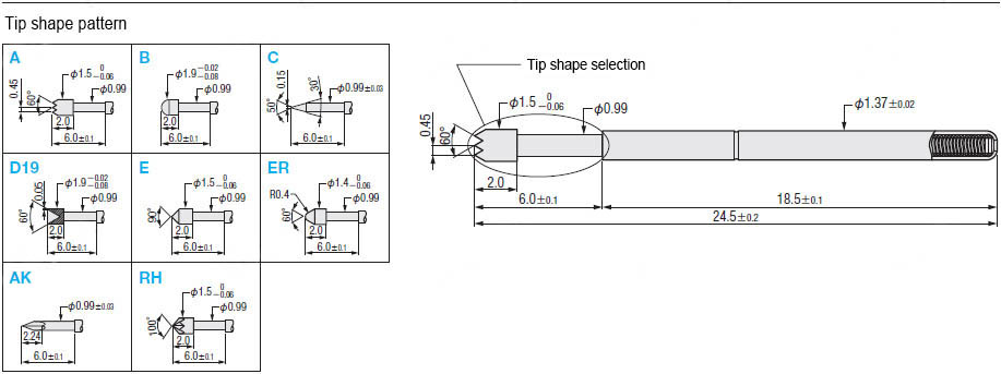
Plunger Tip Shape
- D19 Type
- A Type
- AK Type
- B Type
- C Type
- E Type
- ER Type
- RH Type
-
type
- C-NP604
- C-NP604HD
-
CAD
- 2D
- 3D
Days to Ship
-
- All
- 12 Day(s) or Less
Specify Alterations
NP604 Series Contact Probes Min Pitch2.54mm, Stroke 4.0mm【50 Pieces Per Package】

- Volume Discount
Copy Part Number URL to Clipboard
The part number URL has been copied into your clipboard.-
- Starting From :
- 2,698₹/Unit

-
- Order Qty :
-
-
- Total Price :
- ---
-
- Days to ship :
- ---
Select part number to Order Now/ Add to Cart
-
- Order Qty. :
-
-
- Price :
- ---
-
- Total Price :
- ---
-
- Days to ship :
- ---
-
- Order Qty. :
-
-
- Price :
- ---
-
- Total Price :
- ---
-
- Days to ship :
- ---
-
- Order Qty. :
-
-
- Price :
- ---
-
- Total Price :
- ---
-
- Days to ship :
- ---
-
- Order Qty. :
-
-
- Price :
- ---
-
- Total Price :
- ---
-
- Days to ship :
- ---
Product Description
New at MISUMI? Get 20% Discount on your First Purchase. Click to Register Now
Economy NP604 Series Contact Probes
- Achieve a versatile stroke, perfect for diverse testing applications.
- Minimum mounting pitch for tight spaces.
- Capable of handling robust electrical currents for performance.
- Offers low resistance, enhancing accuracy and efficiency.
- Combines durability with an affordable price for precision testing.

MISUMI Standard

Cheaper Price

Product Variety

3D CAD Support
Product Overview of Contact Probes
Contact Probes is a contact medium for electrical testing, and a high-end precision electronic hardware component.
It can be used to check the conductivity of all electronic circuits.
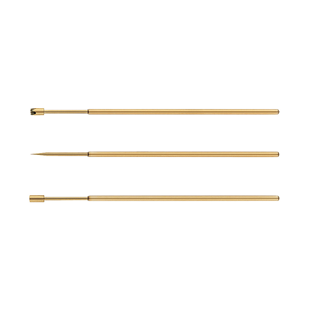
Product Feature of Contact Probes
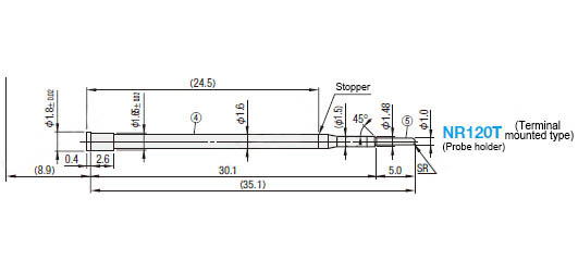
Dimensional Drawing of Contact Probes
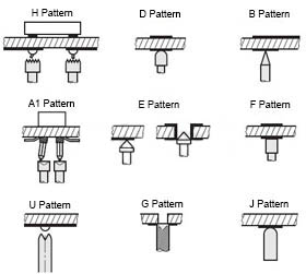
Example Use of Contact Probes
Precautions of Contact Probes
■General environmental conditions
· Operating ambient temperature is 10 to 40 ℃, humidity is 30% below
· Surrounding environment: An environment where there is no dust, corrosive gas, oil, etc. so that the probe is not polluted.
■Stroke condition
· Please apply axial load only, not transverse load.
· Exceeding the specified stroke (2/3 of the full stroke) will significantly reduce the life of the Contact Probes.
· The probe life may be shortened if moving at a speed of more than 60 times /min (constant speed).
■Current application condition
· Please apply current in a static state and in contact with the target contact within the specified stroke.
· The probe life may be significantly reduced if current is applied during operation within the specified stroke, outside the specified stroke, or without contact with the target contact (open circuit).
· The Contact Probes may not meet the maximum allowable current listed in the catalog due to aging and other reasons. Please design to ensure there is enough margin in actual use.
■Voltage application condition
· Please apply voltage in a static state and in contact with the target contact within the specified stroke.
· Do not apply voltage without contact with the target contact (open circuit). Otherwise, it will cause electric discharge when it is about to be touched, causing damage to the probe.
· When applying high voltage to the probe, please strictly observe the application conditions of current and voltage, and pay attention to avoid discharge phenomenon and instantaneous huge current generated during discharge.
■Maximum allowable current
· The maximum allowable current listed in the product catalog is the maximum value of continuous current flowing within 1 minute under the above-mentioned conditions (general environment, stroke, application of current and voltage).
■Contact resistance
· The resistance value listed in the product catalog refers to the representative value measured by applying a current of 10 mA to the Contact Probes and making it contact with the pure silver terminal under the above-mentioned conditions (general environment, stroke, application of current and voltage).
· If the flowing current is too large, the resistance may increase due to the internal aging of the contact or probe.
· After repeated operations within the specified stroke, the resistance may increase due to the aging of the contact or probe.
■Reference number of replacements
· The reference number of replacements listed in the product catalog refers to the reference number for probes that can be used normally when the current is 10mA under the above conditions (general environment, stroke, application of current and voltage).
· When the resistance increases or the spring pressure decreases due to the difference in the operating environment and conditions, the probe may need to be replaced before the reference number is reached. Please replace it in time according to actual usage.
■Spring pressure
· If the Contact Probes temperature exceeds 80 ℃, the spring pressure will drop.
· If the current value is increased, the spring pressure may drop due to the heating of the probe.
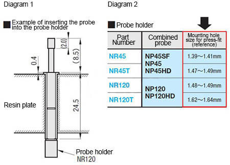
■Mounting hole size for press-fit (reference)
· Reference value only, depending on the material and thickness of the resin plate. Please design referring to the size of the probe holder press-fit part.
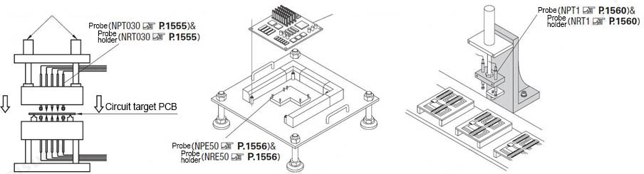
Usage Method of Contact Probes
Please select the product according to the mounting pitch (spacing) of the workpiece to be inspected.
Also, select the probe holder corresponding to the probe.
* The probe is different from the probe holder mounted directly on the resin plate, can be easily disassembled, saving time to replace the probe.
●About the use of the Contact Probes (probe holder)
① Insert the probe holder after opening holes on the resin plate (bakelite board, etc.). (See Diagram 1)
* For the opening size, please refer to the mounting hole size for press-fit as documented on each page. (See Diagram 2)
* If there is clearance between the resin plate and the probe holder, please fix it with adhesive before using it.
② After installation, wire to the probe holder.
* When soldering wires, please be careful not to let the flux flow into the probe holder. Otherwise, the probe may not work.
* Depending on the environment, if there is no space for soldering or wiring, please perform wiring before press-fit.
③ Insert the Contact Probes into the probe holder. (Refer to Diagram 1)
* At this time, if the tip (plunger) part is pressed down forcefully, it may cause damage or deterioration in function. Please be careful.
* Please use within the prescribed stroke (2/3 of the full stroke).
Related Products of Contact Probes
| MISUMI Contact Probes NP120 series matching probe holder product NR120 |
 |
Specification Table of Contact Probes
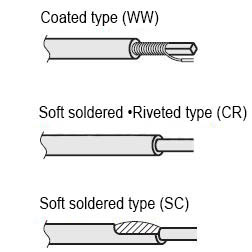
| Part Number | - | Tip Shape | - | Lead Wire Color | - | Lead Wire Length |
| C‐NP120 | - | D |
■ Contact Probes
| Part Number | Mounting Pitch (min) | Full stroke | Spring pressure | Maximum Allowable Current | Resistance | Reference number of replacements | |
| Initial stage | 2/3 stroke | ||||||
| C‐NP604 | 2.54mm | 4mm | 10gf | 110gf | 3A | 50mΩ | 100,000 times |
| C‐NP604HD | 39gf | 160gf | |||||
Part Number
- Incomplete part number.
Please use left hand selections to complete a part number.
| Part Number |
|---|
| C-NP604-A |
| C-NP604-B |
| C-NP604-C |
| C-NP604-D19 |
| C-NP604-E |
| C-NP604-ER |
| C-NP604HD-A |
| C-NP604HD-AK |
| C-NP604HD-B |
| C-NP604HD-C |
| C-NP604HD-D19 |
| C-NP604HD-ER |
| C-NP604HD-RH |
| Part Number | Price | Minimum Order Qty. | Number of pc(s). included in pkg. | Volume Discount | Days to Ship | RoHS | 2/3 Stroke Spring Pressure (Range) (gf) | Plunger O.D. (Ø) | Initial Spring Pressure (Range) (gf) | Initial Spring Pressure (gf) | 2/3 Stroke Spring Pressure (gf) | Plunger Tip Shape |
|---|---|---|---|---|---|---|---|---|---|---|---|---|
₹ 2,843.99 | 1 Pack(s) | 50 Pieces Per Package | Available | 12 Day(s) | 10 | 100.1~150 | 1.5 | 0~10 | 10 | 110 | A Type | |
₹ 2,756.80 | 1 Pack(s) | 50 Pieces Per Package | Available | 12 Day(s) | 10 | 100.1~150 | 1.9 | 0~10 | 10 | 110 | B Type | |
₹ 2,730.75 | 1 Pack(s) | 50 Pieces Per Package | Available | 12 Day(s) | 10 | 100.1~150 | 0.99 | 0~10 | 10 | 110 | C Type | |
₹ 2,758.47 | 1 Pack(s) | 50 Pieces Per Package | Available | 12 Day(s) | 10 | 100.1~150 | 1.9 | 0~10 | 10 | 110 | D19 Type | |
₹ 2,697.71 | 1 Pack(s) | 50 Pieces Per Package | Available | 12 Day(s) | 10 | 100.1~150 | 1.5 | 0~10 | 10 | 110 | E Type | |
₹ 2,751.46 | 1 Pack(s) | 50 Pieces Per Package | Available | 12 Day(s) | 10 | 100.1~150 | 1.4 | 0~10 | 10 | 110 | ER Type | |
₹ 2,814.83 | 1 Pack(s) | 50 Pieces Per Package | Available | 12 Day(s) | 10 | 150.1~200 | 1.5 | 30.1~50 | 39 | 160 | A Type | |
₹ 2,904.35 | 1 Pack(s) | 50 Pieces Per Package | Available | 12 Day(s) | 10 | 150.1~200 | 0.99 | 30.1~50 | 39 | 160 | AK Type | |
₹ 2,747.45 | 1 Pack(s) | 50 Pieces Per Package | Available | 12 Day(s) | 10 | 150.1~200 | 1.9 | 30.1~50 | 39 | 160 | B Type | |
₹ 2,740.44 | 1 Pack(s) | 50 Pieces Per Package | Available | 12 Day(s) | 10 | 150.1~200 | 1 | 30.1~50 | 39 | 160 | C Type | |
₹ 2,700.38 | 1 Pack(s) | 50 Pieces Per Package | Available | 12 Day(s) | 10 | 150.1~200 | 1.9 | 30.1~50 | 39 | 160 | D19 Type | |
₹ 2,697.71 | 1 Pack(s) | 50 Pieces Per Package | Available | 12 Day(s) | 10 | 150.1~200 | 1.4 | 30.1~50 | 39 | 160 | ER Type | |
₹ 2,904.35 | 1 Pack(s) | 50 Pieces Per Package | Available | 12 Day(s) | 10 | 150.1~200 | 1.5 | 30.1~50 | 39 | 160 | RH Type |
| Part Number |
|---|
Loading...
Basic Information
| Type | Contact Probe | Min. Mounting Pitch(mm) | 2.54 | Full Stroke (Range)(mm) | 3~4.5 |
|---|---|---|---|---|---|
| Full Stroke(mm) | 4 | Plunger Material | C1730B | Plunger Surface Treatment | Gold Plating on Nickel Undercoat |
| Plunger Length L1 (Range)(mm) | 5.1~8 | Barrel, Receptacle Material | Phosphor Bronze | Barrel, Receptacle O.D.(Ø) | 1.37 |
| Barrel, Receptacle Length L2 (Range)(mm) | 15.1~20 | Properties | Standard | Allowable Current(A) | 3 |
| Resistance(mΩ) | 50 | Plunger Length(mm) | 6 | Barrel, Receptacle Length(mm) | 18.5 |
- The specifications and dimensions of some parts may not be fully covered. For exact details, refer to manufacturer catalogs .
Frequently asked question (FAQ)
- Question: What are the operating environment conditions for probes?
- Answer: Ambient temperature is 10 to 40℃, humidity is below 30%, and there is no dust, corrosive gas, oil, etc., so that the probe is not polluted.
- Question: Does the center distance chosen for the probe refer to the center distance between two adjacent probes?
- Answer: Yes. If it is less than the minimum mounting pitch, the installation of two adjacent probes interferes with each other.
- Question: If I choose a non-lead type product, how to use it?
- Answer: The customer shall weld the wire by himself.
Payment Method
- Credit Card
-
- Debit Cart
-
- Net Banking
-
- UPI
-
- Cheque on delivery
-
- Online payment
-
Social Media
MISUMI India Contact
Copyright © MISUMI Corporation All Rights Reserved.
- Not a MISUMI customer yet?
- Register and enjoy 20% Off
- on your 1st order! *
- Download CAD data and product data for more than 12 Mio. products.
- Configure your drawing parts in the MISUMI Online Shop and save time and resources.
- Reduce your process costs with the MISUMI Online Shop.


How can we improve?
How can we improve?
Thank you for your time.
Your feedback is essential for our continuous improvement
Privacy Policy
Thank you for your cooperation.
Thank you for your time.
Your feedback is essential for our continuous improvement
Please use the inquiry form.
Privacy Policy