Round Wire Coil Springs, Defection O.D. Referenced, Stainless Steel, Heavy Load
Brand :
MISUMI
Caution
Product Description
New at MISUMI? Get upto ₹10,000 Discount* on Your First Order.Click to Register Now

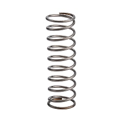
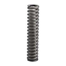
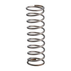
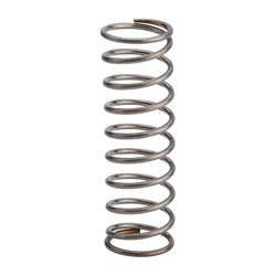
[Features]·This is an outer diameter standard type spring. Note that this product is manufactured with priority given to the outer diameter tolerance. ·Although it is a stainless steel spring, it is magnetic. Please note.
Economy Round Wire Coil Springs
Stainless Steel Heavy Load Reliable
- Superior performance with stainless steel durability.
- O.D. Referenced design ensures exact fit and reliable performance.
- Available in a variety of lengths and diameters to meet your needs.
- High quality at a lower cost, perfect for budget-conscious projects.
- Configurable spring constant and load capacity for tailored solutions.

MISUMI Standard

Cheaper Price

Product Variety

3D CAD Support
Product Overview
♢When purchasing of Round Wire Springs, please note that this spring is the outer diameter standard type, manufactured with priority to the outer diameter tolerance, and suitable for hole installation occasions.
♢Stainless steel springs are also magnetic. Please be careful.
♢Stainless steel springs are also magnetic. Please be careful.
Dimensional Drawings

| Outer Diameter D | φ10 or Less  | Free Length L | 50 or Less | ±1mm | |
φAbove 12  | Above 60 | ±2mm | |||
| Material of Round Wire Springs | |||||
| Material SUS304-WPB Spring Constant ±10% | |||||
Specification Table
■C-UM: Fmax. (allowable displacement) = L×Fa%
 The outer diameter standard type gives priority to guaranteeing the outer diameter, while the inner diameter is for reference only.
The outer diameter standard type gives priority to guaranteeing the outer diameter, while the inner diameter is for reference only.| TYPE | Coil O.D. D - Free Length L | Wire Diameter d | Solid Length | F max. | N{kgf} max. | Fa% | ||
| C-UM | 4- | 5* | 0.4 | 2.2 | 1.75 | 3.4 | {0.35} | 35 |
| 10* | 0.5 | 4.9 | 3.5 | 6.8 | {0.7 } | |||
| 15 | 0.55 | 7.5 | 5.25 | 10.3 | {1.05} | |||
| 20 | 0.6 | 11.1 | 7.0 | 13.7 | {1.4 } | |||
| 5- | 5* | 0.45 | 2.25 | 1.75 | 3.4 | {0.35 } | ||
| 10* | 0.5 | 3.13 | 3.5 | 6.8 | {0.7 } | |||
| 15 | 0.65 | 8.45 | 5.25 | 10.3 | {1.05} | |||
| 20 | 0.65 | 8.45 | 7.0 | 13.7 | {1.4 } | |||
| 30 | 0.7 | 11.9 | 10.5 | 24.0 | {2.45} | |||
| 35 | 0.75 | 16.5 | 12.25 | 20.6 | {2.1 } | |||
| 6- | 5* | 0.55 | 2.7 | 1.7 | 4.9 | {0.5 } | ||
| 10 | 0.7 | 5.6 | 3.5 | 10.8 | {1.1 } | |||
| 15 | 0.75 | 7.4 | 5.2 | 15.7 | {1.6 } | |||
| 20 | 0.75 | 7.4 | 7.0 | 20.6 | {2.1 } | |||
| 25 | 0.85 | 12.8 | 8.7 | 25.5 | {2.6 } | |||
| 30 | 0.85 | 12.8 | 10.5 | 31.4 | {3.2 } | |||
| 35 | 0.9 | 16.7 | 12.2 | 36.3 | {3.7 } | |||
| 40 | 0.9 | 16.8 | 14.0 | 41.2 | {4.2 } | |||
| 8- | 10 | 0.85 | 6.4 | 3.5 | 10.8 | {1.1 } | ||
| 15 | 0.9 | 7.9 | 5.3 | 15.7 | {1.6 } | |||
| 20 | 0.9 | 7.9 | 7.0 | 20.6 | {2.1 } | |||
| 25 | 0.9 | 7.9 | 8.8 | 25.5 | {2.6 } | |||
| 30 | 1.0 | 12.0 | 10.5 | 31.4 | {3.2 } | |||
| 35 | 1.0 | 12.0 | 12.3 | 36.3 | {3.7 } | |||
| 10- | 10 | 0.9 | 5.2 | 3.5 | 10.8 | {1.1 } | ||
| 15 | 1.0 | 7.3 | 5.3 | 15.7 | {1.6 } | |||
| 20 | 1.0 | 7.3 | 7.0 | 20.6 | {2.1 } | |||
| 25 | 1.1 | 10.5 | 8.8 | 25.5 | {2.6 } | |||
| 30 | 1.1 | 10.5 | 10.5 | 31.4 | {3.2 } | |||
| 13- | 15 | 1.2 | 8.4 | 5.3 | 15.7 | {1.6 } | ||
| 20 | 1.3 | 11.1 | 7.0 | 20.6 | {2.1 } | |||
| 25 | 1.3 | 11.1 | 8.8 | 25.5 | {2.6 } | |||
| 40 | 1.4 | 15.1 | 14.0 | 41.2 | {4.2} | |||
| 20- | 30 | 1.9 | 13.3 | 10.5 | 52.0 | {5.3 } | ||
kgf (load)=N/mm (spring constant)×0.101972×F (displacement)
{kgf}=N×0.101972
{kgf}=N×0.101972
■C-UH: Fmax. (allowable displacement) = L×Fa%
The outer diameter standard type gives priority to guaranteeing the outer diameter, while the inner diameter is for reference only
The outer diameter standard type gives priority to guaranteeing the outer diameter, while the inner diameter is for reference only| TYPE | Coil O.D. D - Free Length L | Wire Diameter d | Solid Length | F max. | N{kgf} max. | Fa% | ||
| C-UH | 4- | 5* | 0.45 | 2.7 | 1.5 | 4.4 | { 0.45} | 30 |
| 10* | 0.5 | 3.8 | 3.0 | 8.8 | { 0.9 } | |||
| 15 | 0.6 | 8.1 | 4.5 | 13.2 | { 1.35} | |||
| 5- | 5* | 0.55 | 3.3 | 1.5 | 4.4 | { 0.45 } | ||
| 10 | 0.6 | 4.65 | 3.0 | 8.8 | { 0.9 } | |||
| 15 | 0.6 | 4.65 | 4.5 | 13.2 | { 1.35} | |||
| 25 | 0.75 | 11.81 | 7.5 | 22.1 | { 2.25} | |||
| 6- | 5* | 0.65 | 3.2 | 1.5 | 8.8 | { 0.9 } | ||
| 10 | 0.7 | 3.9 | 3.0 | 17.7 | { 1.8 } | |||
| 15 | 0.85 | 7.7 | 4.5 | 26.5 | { 2.7 } | |||
| 20 | 0.9 | 9.7 | 6.0 | 35.3 | { 3.6 } | |||
| 25 | 1.0 | 15.5 | 7.5 | 44.1 | { 4.5 } | |||
| 30 | 1.0 | 15.5 | 9.0 | 53.0 | { 5.41 } | |||
| 8- | 10 | 0.9 | 5.3 | 3.0 | 17.7 | { 1.8 } | ||
| 15 | 0.9 | 5.3 | 4.5 | 26.5 | { 2.7 } | |||
| 20 | 1.1 | 11 | 6.0 | 35.3 | { 3.6 } | |||
| 25 | 1.1 | 11 | 7.5 | 44.1 | { 4.5 } | |||
| 30 | 1.2 | 15.9 | 9.0 | 53.0 | { 5.4 } | |||
| 10- | 15 | 1.1 | 6.9 | 4.5 | 26.5 | { 2.7 } | ||
| 20 | 1.2 | 9.3 | 6.0 | 35.3 | { 3.6 } | |||
| 25 | 1.2 | 9.3 | 7.5 | 44.1 | { 4.5 } | |||
| 30 | 1.3 | 12.7 | 9.0 | 53.0 | { 5.4 } | |||
| 35 | 1.4 | 17.5 | 10.5 | 61.8 | { 6.3 } | |||
| 13- | 15 | 1.5 | 9.2 | 4.5 | 44.1 | { 4.5 } | ||
| 20 | 1.5 | 9.2 | 6.0 | 58.8 | { 6 } | |||
| 25 | 1.5 | 9.2 | 7.5 | 73.5 | { 7.5 } | |||
| 30 | 1.8 | 18 | 9.0 | 88.3 | { 9 } | |||
| 50 | 2.0 | 28.5 | 15.0 | 147.0 | {15.0 } | |||
| 16- | 45 | 2.2 | 25.1 | 13.5 | 132.4 | { 13.51 } | ||
| 20- | 30 | 2.3 | 13.8 | 9.0 | 132.4 | { 13.51 } | ||
| 35 | 2.5 | 18.8 | 10.5 | 154.9 | { 15.81 } | |||
| 40 | 2.5 | 18.8 | 12.0 | 176.5 | { 18.01 } | |||
| 45 | 2.8 | 29.4 | 13.5 | 199.1 | { 20.32 } | |||
Both ends of C-UM/C-UH models with * are not ground.● Calculation method of laps (reference value):
Total number of laps = solid length ÷ wire diameter (d)-1
Effective laps=total number of laps-2
*The number of laps is a reference value. There will be some deviations among batches.
The solid length is a reference value. There will be slight differences among batches.Moreover, if it is used under the limit condition of the solid length, it may cause the spring to be deformed or be damaged after using only a limited number of times.
Be sure to use within the allowable displacement Fmax.(mm)■Spring Constant The spring constant
D12 is for C-UY・C-UR・C-UF・C-UBB only. D14 is for C-UBB only.| Type | C-UV | C-UY | C-UR | C-UF | C-UL | C-UTT | C-UM | C-UH | C-UBB | |||||||||||||||||||
| D | ||||||||||||||||||||||||||||
| 2 | 0.05{0.005} | 0.2{0.02} | 0.3{0.03} | 0.5{0.05} | ||||||||||||||||||||||||
| 3 | N/mm 0.05 {kgf/mm}{0.005} | N/mm 0.098 {kgf/mm}{0.01} | N/mm 0.29 {kgf/mm} {0.03} | N/mm 0.49 {kgf/mm} {0.05} | N/mm 0.98 {kgf/mm} {0.1} | 1.5{0.15} | ||||||||||||||||||||||
| 4 | 2.0 {0.2} | 2.9{0.3} | 4.9{0.5} | |||||||||||||||||||||||||
| 5 | N/mm 2.0 {kgf/mm} {0.2} | |||||||||||||||||||||||||||
| 6 | N/mm 2.9 {kgf/mm} {0.3} | N/mm 5.9 {kgf/mm} {0.6} | N/mm 9.8 {kgf/mm} {1.0} | |||||||||||||||||||||||||
| 8 | ||||||||||||||||||||||||||||
| 10 | N/mm 0.2 {kgf/mm} {0.02} | |||||||||||||||||||||||||||
| 12 | ||||||||||||||||||||||||||||
| 13 | N/mm 9.8 {kgf/mm} {1.0} | N/mm 19.6 {kgf/mm} {2.0} | ||||||||||||||||||||||||||
| 14 | ||||||||||||||||||||||||||||
| 16 | ||||||||||||||||||||||||||||
| 20 | 0.3{0.03} | 0.5{0.05} | 0.98{0.1} | 2.9{0.3} | 3.9{0.4} | 4.9{0.5} | 14.7{1.5} | 29.4{3.0} | ||||||||||||||||||||
| Fmax. | F=L×70% | F=L×75% | F=L×60% | F=L×45% | F=L×40% | F=L×40% | F=L×35% | F=L×30% | F=L×25% | |||||||||||||||||||
Product Features
Different from ordinary springs on the market, MISUMI Round Wire Springs are more precise and refined, divided into the inner diameter standard type and the outer diameter standard type, the former of which is manufactured giving priority to the inner diameter tolerance while the latter is manufactured giving priority to the outer diameter tolerance.
Select an appropriate Round Wire Springs type according to the actual installation situation, and refer to the published content for the specific inner and outer diameter tolerance values.
* The solid length is a reference value. If it is used under the limit condition of the solid length, the spring may be deformed, or damaged after using only a limited number of times. Therefore, use within the allowable displacement Fmax.(mm).
To increase the usage count, it is recommended to use the spring up to 70% of the allowable displacement Fmax..
 *The test data are obtained through testing by our company, which are for reference only. *Generic products on the market are similar products randomly purchased by our company from online or offline markets | 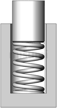 Installation Diagram of Outer Diameter Standard Type Round Wire Coil Spring |
Precautions
Precautions for use of Round Wire Springs
Operating temperature of Round Wire Springs
SWP-A……Normal temperature (0~40℃)
Stainless steel……-10~100℃
Spring oil tempered steel wire……Normal temperature (0~40℃)
*If the spring is used under conditions exceeding the above temperature, the load value may decrease due to usage conditions.
*When used in an environment with high and low temperature differences and humidity such as outdoors, it is recommended to choose stainless steel products.
* Heat-resistant springs can also be used. For details, refer to the Plastic Mold Components Catalog.
Stainless steel springs are also magnetic. Please be careful.
Example of Use

Hole Reference Positioning Mechanism
A Round Wire Springs is mechanism for positioning the workpiece based on the hole reference.
Loosening during positioning can be reduced by using a tapered pin to eliminate the deviation caused by the tolerance of each workpiece hole.
Select the compression spring to move from the beginning of the positioning contact with the workpiece.
Related Products
 |  |  |
| (Economy series) Round Wire Springs - Outer Diameter Standard Stainless Steel, Ultra Heavy Load, Spring Constant 4.9 to 29.4N/mm | (Economy series) Round Wire Springs - Inner Diameter Standard Stainless Steel, Light Load, Spring Constant 0.29 to 0.49 N/mm | (Economy series) Round Wire Springs - Outer Diameter Standard Stainless Steel, Light Load, Spring Constant 0.5 to 3.9 N/mm |
| Reason for Recommendation: MISUMI Basic Round Wire Springs, Outer Diameter Standard Type, Ultra Heavy Load Type | Reason for Recommendation: MISUMI Basic Round Wire Springs, Inner Diameter Standard Type, Light Load Type | Reason for Recommendation: MISUMI Basic Round Wire Springs, Outer Diameter Standard Type, Light Load Type |