Aluminum Frame 8-45 Series Rectangular 45 × 90 mm 4 Side Slots - A6N01SS-T5 Aluminum
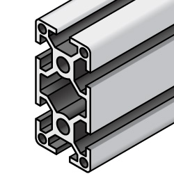
Brand :
MISUMI
Caution
- The aluminum extrusion of this product is intended for indoor use. Since MISUMI and other manufacturers' aluminum extrusions are not compatible, we recommend using extrusions and related components from the same manufacturer.
Product Description
8-45 Series 45 mm square, 2 slot aluminum extrusion.
■8-45 Series:
The aluminum extrusion with 10 mm slot width. Applicable to M8 bolts.
Cut surface and alteration sections are not surface treated.
Dimensional Drawing of Aluminum Frames
| EFS >(standard type) | HFS >(standard type) | HFSL >(lightweight type) | ||
 |  |  | ||
| [ ! ]Please use HSCA8 for the groove cover of HFSL8-4590 |
GFS(high rigidity type)
 Fixed length Aluminum Frames have no tolerance regulations
8-45 Series |
 |
■The 8-45 series has
a groove width of 10±0.36 mm and is suitable for M8 bolts.
[ ! ] No surfacetreatment is applied to cut surfaces or additionally machined areas.
[ ! ] If an end tap is specified, it willbe machined in the area circled in red.
a groove width of 10±0.36 mm and is suitable for M8 bolts.
[ ! ] No surfacetreatment is applied to cut surfaces or additionally machined areas.
[ ! ] If an end tap is specified, it willbe machined in the area circled in red.
For information regarding dimensional tolerances
Groove details (HFS/CAF/GFS)
Groove details (EFS)
Groove bottom details
Groove bottom details
(HFS/CAF type)
(GFS type)
(EFS type)
Enlarged view of part A
Enlarged view of part A
Enlarged view of part A

*Lightweight type (HFSL) is 5.5.
Specified Length Aluminum Frames Specifications Table (Additional Processing: Possible)
| Model | − | L | |
| HFS8-4590 | − | 800 |
| type | Material | Surface Treatment | Model | L specified in 0.5mm increments (tolerance ±0.5mm) | Mass kg/m | Cross-sectional area >2 | Moment of inertia >4 | |
| ℓx | ℓy | |||||||
| HFS | A6005CSS-T5 | White anodized aluminum | HFS8-4590 | 5 0 to 4 0 0 0 | 4.14 | 1534 | 32.2>104 | 124.>104 |
| HFS | A6005CSS-T5 | Black anodized aluminum | H F S B 8 -4 5 9 0 | 5 0 to 4 0 0 0 | 4.14 | 1534 | 32.2>104 | 124.>104 |
| HFS | A6005CSS-T5 | Clear coating | C A F 8 - 4 5 9 0 | 5 0 to 4 0 0 0 | 4.14 | 1534 | 32.2>104 | 124.>104 |
| HFS | A6005CSS-T5 | Baked finish (yellow) *1 | HFSY8-4590 | 5 0 to 4 0 0 0 | 4.14 | 1534 | 32.2>104 | 124.>104 |
| HFSL | A6005CSS-T5 | White anodized aluminum | H F S L 8 -4 5 9 0 | 5 0 to 4 0 0 0 | 2.98 | 1101 | 22.8>104 | 87.1>104 |
| EFS | A6005CSS-T5 | White anodized aluminum | E F S 8 -4 5 9 0 | 5 0 to 4 0 0 0 | 3.75 | 1390 | 32.6>104 | 125.>104 |
| EFS | A6005CSS-T5 | Black anodized aluminum | E F S B 8 -4 5 9 0 | 5 0 to 4 0 0 0 | 3.75 | 1390 | 32.6>104 | 125.>104 |
| GFS | A6061SS-T6 equivalent | White anodized aluminum | G F S 8 -4 5 9 0 | 5 0 to 4 0 0 0 | 5.22 | 1935 | 42.9>104 | 163.>104 |
[ ! ] If you require a length of 6000 mm without anodizing
Fixed Length Aluminum Frames Specifications Table (Effective Length 4000mm)
[ ! ]Fixed-length Aluminum Frames have a format with K at the beginning of the format code for each Aluminum Frames.
[ ! ] *1The color of KHFSY8 is D22-80V (Japan Paint Manufacturers Association, reference Munsell value 2.5Y8/12).
[ ! ] *2 An effective length of 4000 mm means that the Aluminum Frames has aneffective length of 4000 mm or more that can actually be used.
The actual length including the gripping area is 4000 mm or more (it will be several tens of mm longer).
The fixed-length Aluminum Frames is a Aluminum Frames that the customer cuts to their own size, so the exactlength cannot be specified.
[ ! ]A heat resistance temperature of up to 70°C is recommended. Continuousexposure to temperatures above 100°C will cause bending due to the load.
However, temporary high temperatures such as steam can withstand temperatures up to 100°C.
| Model | − | L | |
| KHFS8−4590 | − | 4000 |
| type | Material | Surface Treatment | Model | Lmm (no tolerance specified) *2 | Cross-sectional area mm 2 | Moment of inertia mm 4 | |
| ℓx | ℓy | ||||||
| HFS | A6005CSS-T5 | White anodized aluminum | K H F S 8 -4 5 9 0 | 4 0 0 0 | 1534 | 32.29× 10⁴ | 124.7× 10⁴ |
| HFS | A6005CSS-T5 | Black anodized aluminum | K H F S B 8 -4 5 9 0 | 4 0 0 0 | 1534 | 32.29× 10⁴ | 124.7× 10⁴ |
| HFS | A6005CSS-T5 | Clear coating | K C A F 8 -4 5 9 0 | 4 0 0 0 | 1534 | 32.29× 10⁴ | 124.7× 10⁴ |
| HFS | A6005CSS-T5 | Baked finish (yellow) *1 | KHFSY8-4590 | 4 0 0 0 | 1534 | 32.29× 10⁴ | 124.7× 10⁴ |
| HFSL | A6005CSS-T5 | White anodized aluminum | K H F S L 8 -4 5 9 0 | 4 0 0 0 | 1101 | 22.87× 10⁴ | 87.16× 10⁴ |
| EFS | A6005CSS-T5 | White anodized aluminum | K E F S 8 -4 5 9 0 | 4 0 0 0 | 1390 | 32.67× 10⁴ | 125.3× 10⁴ |
| EFS | A6005CSS-T5 | Black anodized aluminum | K E F S B 8 -4 5 9 0 | 4 0 0 0 | 1390 | 32.67× 10⁴ | 125.3× 10⁴ |
| GFS | A6061SS-T6 equivalent | White anodized aluminum | K G F S 8 -4 5 9 0 | 4 0 0 0 | 1935 | 42.99× 10⁴ | 163.4× 10⁴ |
[ ! ] *2 An effective length of 4000 mm means that the Aluminum Frames has aneffective length of 4000 mm or more that can actually be used.
The actual length including the gripping area is 4000 mm or more (it will be several tens of mm longer).
The fixed-length Aluminum Frames is a Aluminum Frames that the customer cuts to their own size, so the exactlength cannot be specified.
[ ! ]A heat resistance temperature of up to 70°C is recommended. Continuousexposure to temperatures above 100°C will cause bending due to the load.
However, temporary high temperatures such as steam can withstand temperatures up to 100°C.
Alterations of Aluminum Frames (Specified Length Only, Fixed Length Not Possible)
[ ! ]By using the various alterations listed below, MISUMI's specified length Aluminum Frames can be assembled withgreater flexibility.
Some Aluminum Frames cannot be applied depending on the type and size. Please check the price list on eachalteration page to see if it is applicable.
Items marked with "-" in the price list cannot be applied.
Some Aluminum Frames cannot be applied depending on the type and size. Please check the price list on eachalteration page to see if it is applicable.
Items marked with "-" in the price list cannot be applied.
| classification | Additional Work name | Alteration code example | How to Use | Content |
|---|---|---|---|---|
| > End face tapping | End face tap (center hole) | LTP/RTP/TPW LHP/RHP/HPW |  | The Aluminum Frames is tapped. ■HFS/EFS type LTP/RTP/TPW: M12 depth 18 mm (helisert inserted) LHP/RHP/HPW: M10 depth 18 mm (helisert inserted) ■GFS type LTP/RTP/TPW: M12 depth 36 mm LHP/RHP/HPW: M8 depth 15 mm (helisert inserted) Blind joints ( screw joints simple joints) thatrequire this processing |
| > Change cutting method | High-precision cutting | SC |  | The tolerance of the overall length L has been changed from L±0.5 to L±0.2, allowing for high-precision cutting. *Only applicable to L≦1500 |
| 45 degree cut | L□T45 R□T45 |  | The cut is made at a 45-degree angle. 45-degree cuts cannot be specified in the same direction with otheralterations. Example: HFS6-3030-500- L TP- LAT45 ⇒ ✖ (alterations in the same direction (left)) HFS6-3030-500- L TP- R AT45 ⇒ 〇 (separatealterations on left and right) [ ! ] If you would like to cut at an angle other than 45 degrees | |
| > Wrench Drilling | Fixed position wrench hole | LCH/LCV/LCP RCH/RCV/RCP |  | This additional processing is required to drill a wrench hole (φ8) in accordance with the position of the tap onthe end face of the mating Aluminum Frames when fastening a blind joint that assembles Aluminum Frames into an Lshape. Blind joints that require this processing (screw joints / single joints / tapping joints) |
Hole position shifted by the thickness of the Aluminum Frames cap | FL FR |  | The hole position for the additional fixed position wrench hole is moved by the thickness of the Aluminum Framescap (3 mm). This prevents the Aluminum Frames cap from protruding when assembled at a corner. | |
| Wrench holes at specified positions | AH/BH/CH/DH/EH AV/BV/CV/DV/EV AP/BP/CP/DP/EP |  | This is an additional process to drill a wrench hole (φ8) at any position. It can be used when fastening blindjoints at locations other than the Aluminum Frames end. ・ Up to five holes can be drilled in each of thehorizontal, vertical, and cross directions. [!] If you require six or morewrench holes | catalog |
| > Counterbore Drilling | Specified position counterbored hole | Z8-XA○○ Z12-YA○○ |  | This is an additional process to drill a counterbore hole (select from Z6, Z8, or Z12) at any position. Z6: Through hole φ6.5, counterbore φ11, Z8: Through hole φ9, counterbore φ14, Z12: Through hole φ13,counterbore φ19 . Up to five holes can be drilled in one direction. For Aluminum Frames with multiplerows of grooves on one surface, counterbore holes will be machined in all grooves. [ ! ]If you require more than six counterbore holes or to change the direction of the counterbore holes. |
| > Drilling holes specifically for blind joints | D hole | LDH/LDV RDH/RDV |  | Drill the holes required for fastening a single joint. (Single joint) |
| S hole | LSH/LSV RSH/RSV |  | Drills holes required for fastening first-in-place double joints (first-in-place double joints). | |
| M hole | LMH/LMV RMH/RMV |  | Drills holes required for connecting post-assembly double joints and center joints. (Post-assembly double joints / center joints) | |
| > Other processing | GFS series end face tap | LTS/RTS/TSW |  | We perform the tapping required to attach end plates specifically for high-rigidity Aluminum Frames. ( High-rigidity plates ) |
| C-chamfered end | CW |  | The outer periphery of the Aluminum Frames end face is chamfered. | |
| Sticking stickers | ZZZ |  | A sticker printed with the catalog number etc. is attached to the aluminum Aluminum Frames. There are restrictions on the number of characters etc., but it is also possible to print the customer'sserial number and unit number. |
8-45 Series Related Parts of Aluminum Frames
■Aluminum Aluminum Frames accessories
Product name | bracket | Blind Joint | nut | Frame cap | Groove cover | Conductive washer |
|---|---|---|---|---|---|---|
photograph |  |  |  |  |  |  |
Product page |
■List of compatible Aluminum Frames caps
Frame model number | Compatible Aluminum Frames caps | |||||
Product Type | color | Thickness | Model number | Number of uses | ||
| HFS8-4590 HFSB8-4590 CAF8-4590 HFSL8-4590 HFSY8-4590 EFS8-4590 EFSB8-4590 Fixed length Aluminum Frames (model numbers starting with K) are also the same. |  | Cap stopper | black | 3 | 1 | |
Light gray | 3 | 1 | ||||
 | Cap stopper (long leg type) | black | 3 | 1 | ||
Light gray | 3 | 1 | ||||
 | bolted | black | 3 | 1 | ||
Light gray | 3 | 1 | ||||
 | Cap stopper | black | 3 | 2 | ||
Light gray | 3 | 2 | ||||
 | Cap stopper (long leg type) | black | 3 | 2 | ||
| The same applies to the GFS8-4590 fixed length Aluminum Frames (model number starting with K). |  | Cap stopper | black | 3 | 1 | |
Light gray | 3 | 1 | ||||
 | Bolt mounting (high rigidity plate type) requires special additional processing. | silver color | 2 | 1 | ||
Selection Support Information of Aluminum Frames
■Frame connection methodsFrame
connection methods can be broadly divided into the following two types.
connection methods can be broadly divided into the following two types.
bracket | Blind Joint | ||
Connection example |  |  | |
Features | - Connects outside the Aluminum Frames - Can be moved to any position - Not aesthetically pleasing | ・Connects inside the Aluminum Frames ・Aesthetically pleasing ・Requires processing of the AluminumFrames |
■Additional tapping of end faces (8-45 series 45 x 90)
Center section (2 holes) (no corners)
Center section (2 holes) (no corners)
type | Size and Position | left | Right side | both sides | cross section | |
NEFS EFS HFS NFSL HFSL | M12 depth 18 (φ12.5 is helical insert) | LTP | RTP | TPW | ||
M10 depth 18 (helisert inserted) | LHP | RHP | HPW | |||
GFS GNFS | M12 depth 36 | LTP | RTP | TPW | ||
M8 depth 15 (helisert inserted) | LHP | RHP | HPW | |||
Tap position |  |  |  |  | ||
■How to think about the allowable guideline load (deflection) for Aluminum Frames
[!]The allowable guideline load is the load that causes the Aluminum Frames to deflect within 1 mm per 1000 mm oflength.
Deflection exceeding this will not cause damage, but it should be considered the maximum practical deflection.(The allowable guideline deflection is proportional to the length. For example, 500 mm = 0.5 mm, 2000 mm = 2 mm.)Please refer to
the aluminum Aluminum Frames strength guideline table or the simplified deflection calculation table/deflectioncalculation formula for your reference.

[!]The allowable guideline load is the load that causes the Aluminum Frames to deflect within 1 mm per 1000 mm oflength.
Deflection exceeding this will not cause damage, but it should be considered the maximum practical deflection.(The allowable guideline deflection is proportional to the length. For example, 500 mm = 0.5 mm, 2000 mm = 2 mm.)Please refer to
the aluminum Aluminum Frames strength guideline table or the simplified deflection calculation table/deflectioncalculation formula for your reference.
