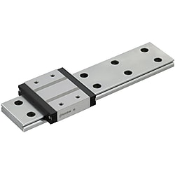
Miniature Linear Guides - Wide Rails - Standard Blocks, Light Preload / Slight Clearance
Caution
- Since 2017, we have been gradually changing the product appearance. There is a possibility that both the old and new versions may be delivered together, but there is no difference in functionality.Regarding the appearance change of MISUMI linear guides
- If you would like to use two shafts in parallel as the alteration/WC, please order an even number (2, 4, etc.).
- [Stoke resumed] The restriction on the application of L size has been removed.
Product Description
Miniature Linear Guides - Wide Rails - Standard Blocks, Light Preload / Slight Clearance
These linear guides or linear slides are factory automation components. They offer a wide variety of sizes to choose from.
This is a wide rail standard block type that meets the industry standard.
Please consider the light preload type, which has excellent precision and rigidity.
Manufactured by Suruga Production Platform Co., Ltd.
Suruga Production Platform develops its business based on "precision processing technology" that requires precision in microns.
Suruga's precision machine parts are also used in cutting-edge fields such as the aerospace and automotive industries.
[Features]
- Rail Length Minimum/Maximum (mm.): 50 and 670
- Assembly Height (mm.): 6.5, 9, 12, 14, and 16
- Accuracy Standards : Standard Grade, High Grade and Precision Grade
- Rail Type : Wide Rail
- Material: Stainless Steel 56HRC
[Applications]
- It is used in a variety of machines such as CNC machines, 3D printers, measuring instruments, and so on.
Miniature Linear Guides, Wide Rails, Standard Blocks
| Rail / block Surface treatment Material (hardness) *1 | Rail length Type *2 | No. of blocks *3 | Preload / accuracy A | Height (H) B | Grease C *4 | ||
|---|---|---|---|---|---|---|---|
| Light preload | Slight clearance | ||||||
| Precision grade | High grade | Normal grade | |||||
| No surface treatment Stainless steel [SUS440C equivalent] (56HRC–) | Standard length (fixed length) | 1 | SSEBWV | SSEBW | SSEBWZ | 6.5 9 12 14 16 | Blank: standard G: G grease L: L grease Y: Y grease H: H grease |
| 2 | SSE2BWV | SSE2BW | SSE2BWZ | ||||
| 1 mm increments (configurable length) | 1 | SSEBWLV | SSEBWL | SSEBWLZ | |||
| 2 | SSE2BWLV | SSE2BWL | SSE2BWLZ | ||||
| Low-temperature black chrome plating Stainless steel [SUS440C equivalent] (56HRC–) | Standard length (fixed length) | 1 | - | RSEBW | - | 9 12 14 16 | Blank: standard G: G grease L: L grease Y: Y grease H: H grease |
| 2 | - | RSE2BW | - | ||||
| 1 mm increments (configurable length) | 1 | - | RSEBWL | - | |||
| 2 | - | RSE2BWL | - | ||||
- *1 For the material of each part, see MISUMI linear guide product information.
- *2 If the required rail length is not available as a standard (fixed) length, select 1 mm increments (configurable length).
- *3 For 3- or 4-block products, select the 1-block part number and specify "B3 (3 blocks)" or "B4 (4 blocks)" as additional machining.
- *5 Low-temperature black chrome plated products are limited to a maximum of 2 blocks.
- H6.5 is not available in normal grade or precision grade.
- Heat resistance temperature is −20 to 80°C.
- Not possible: Blocks and rails cannot be purchased separately. (They are also not available through the non-catalog product service.)
- Part number configuration
| Type | Height H | Grease | - | Rail length L | - | Additional machining | |||
|---|---|---|---|---|---|---|---|---|---|
| A | B | C | |||||||
| SSEBW | 12 | - | 260 | (SSEBW12-260) | |||||
| SSE2BWL | 12 | G | - | 578 | - | (SSE2BWL12G-578) | |||
| SSEBWLZ | 12 | Y | - | 578 | - | B4 | (SSEBWLZ12Y-578-B4) |
- H6.5
- H6.5 · 9 · 12 · 14
- H16
- Values in ( ) are the number of tapped holes for H6.5.
- For configurable-L types, the G dimension differs from the table below.
- Not possible: Blocks and rails cannot be purchased separately. (They are also not available through the non-catalog product service.)
H and W2 dimensional accuracy
| Type | Accuracy standard | Assembled height (H) | Accuracy (μm) | ||||
|---|---|---|---|---|---|---|---|
| Precision grade | High grade | Normal grade | |||||
| Surface treatment None | Low-temperature black chrome plating | ||||||
| Miniature linear guide | Dimensional tolerance of height H | 6–20 | ±10 | ±20 | +30 -20 | ±20 | |
| Pair variation of height H | 7 | 15 | 15 | 40 | |||
| Dimensional tolerance of width W2 | ±15 | ±25 | ±25 | ±25 | |||
| Pair variation of width W2 | 10 | 20 | 20 | 40 | |||
L dimensional tolerance (unit: mm)
| L range | Tolerance |
|---|---|
| 25 ≤L≤ 400 | 0 -0.8 |
| 400 <L≤ 1000 | 0 -1.0 |
- Pair variation of height is the difference between the minimum and maximum height of multiple blocks assembled on one rail.
- Pair variation of width is the difference between the minimum and maximum width between the rail and the multiple blocks assembled on it.
- The accuracy of low-temperature black chrome plated miniature linear guides is as shown above.
- The sliding resistance is higher than normal: approx. 1.2 N or less.
Dimensional tolerances of other symbols
| Dimension range | Tolerance (mm) | |
|---|---|---|
| Over | Up to | |
| 0.5 | 3 | ±0.1 |
| 3 | 6 | ±0.1 |
| 6 | 30 | ±0.2 |
| 30 | 120 | ±0.3 |
| 120 | 400 | ±0.5 |
| 400 | 1000 | ±0.8 |
| 1000 | 2000 | ±1.2 |
Per JIS B 0405-1991 class m (medium)
Specifications
| Type | L *5 | Block dimensions | Rail dimensions | |||||||||||||||
|---|---|---|---|---|---|---|---|---|---|---|---|---|---|---|---|---|---|---|
| Type | H | W | L1 | B | C | S×ℓ | L2 | K | Cb | W1 | W2 | H1 | Ca | Counterbored hole | F | G *6 | ||
| 1 block | 2 blocks | d1×d2×h | ||||||||||||||||
| SSEBW SSEBWV SSEBWZ SSEBWL SSEBWLV SSEBWLZ RSEBW RSEBWL | SSE2BW SSE2BWV SSE2BWZ SSE2BWL SSE2BWLV SSE2BWLZ RSE2BW RSE2BWL | 6.5 | 50–170 (70) | 17 | 21 | 13 | - | M2.5×1.5 | 13.3 | 5 | 0.3 | 10 | 3.5 | 4 | 0.3 | 3×5×1.6 | 20 | 5 |
| 9 | 50–380 (110) | 25 | 31.1 | 18 | 12 | M2.6×2.5 | 20.1 | 7 | 0.3 | 14 | 5.5 | 5.2 | 0.5 | 3.5×6×3.2 | 30 | 10 | ||
| 12 | 50–620 (110) | 30 | 38 | 21 | 12 | M2.6×3 | 27 | 9 | 0.3 | 18 | 6 | 7.5 | 0.5 | 3.5×6×4.5 | 30 | 10 | ||
| 14 | 70–990 (150) | 40 | 44.3 | 28 | 15 | M3×3.5 | 30.1 | 11 | 0.5 | 24 | 8 | 8 | 0.5 | 4.5×8×4.5 | 40 | 15 | ||
| 16 | 70–990 (190) | 60 | 55 | 45 | 20 | M4×4.5 | 40 | 13 | 0.5 | 42 | 9 | 9.5 | 0.5 | 4.5×8×4.5 | 40 | 15 | ||
- *5 Values in ( ) are the minimum rail lengths for 2-block types.
- *6 For configurable-L types, both ends of the rail are cut equally. In that case the G dimension differs from the table.
- H dimension 6.5 comes with screws for rail mounting (M2.5×7). Recommended: cross-recessed pan head machine screw No. 0, type 1.
- Other sizes do not include them.
- Align and fix the reference surfaces (the side with the straight groove) of both the rail and the block correctly. For details, see "Mounting and handling" below.
- Waterproof specifications are not available.
- Standard rail lengths (fixed length)
- The table below lists the standard rail lengths for each size.
| Height | Rail length | |||||||||||||||||||||||
|---|---|---|---|---|---|---|---|---|---|---|---|---|---|---|---|---|---|---|---|---|---|---|---|---|
| ( H ) | ( L ) | |||||||||||||||||||||||
| 6.5 | (50) | 70 | 90 | 110 | 130 | 150 | 170 | |||||||||||||||||
| 9 | (50) | (80) | 110 | 140 | 170 | 200 | 230 | 260 | 290 | 320 | 350 | 380 | ||||||||||||
| 12 | (50) | (80) | 110 | 140 | 170 | 200 | 230 | 260 | 290 | 320 | 350 | 380 | 410 | 440 | 470 | 500 | 530 | 560 | 590 | 620 | ||||
| 14 | (70) | (110) | 150 | 190 | 230 | 270 | 310 | 350 | 390 | 430 | 470 | 510 | 550 | 590 | 630 | 670 | 710 | 750 | 790 | 830 | 870 | 910 | 950 | 990 |
| 16 | (70) | (110) | (150) | 190 | 230 | 270 | 310 | 350 | 390 | 430 | 470 | 510 | 550 | 590 | 630 | 670 | 710 | 750 | 790 | 830 | 870 | 910 | 950 | 990 |
Lengths in ( ) are not available as standard products for 2-block types.
Basic load ratings, static allowable moments, mass, frictional resistance (required thrust) and sliding resistance (seal resistance)
kgf=N×0.101972
| Height (H) | Basic load rating*8 | Static allowable moment | Mass | |||||||
|---|---|---|---|---|---|---|---|---|---|---|
| C (dynamic) kN | Co (static) kN | 1 block | 2 blocks in contact*9 | Block kg | Guide rail kg/m | |||||
| MA N·m | MB N·m | MC N·m | MA N·m | MB N·m | MC N·m | |||||
| 6.5 | 0.5 | 0.9 | 2.0 | 2.0 | 4.0 | 8.3 | 8.3 | 8.0 | 0.006 | 0.28 |
| 9 | 1.4 | 2.2 | 7.8 | 7.8 | 15.5 | 21.7 | 21.7 | 31.0 | 0.02 | 0.50 |
| 12 | 2.3 | 3.7 | 13.7 | 16.3 | 30.4 | 43.7 | 43.7 | 60.8 | 0.04 | 0.96 |
| 14 | 3.5 | 5.3 | 20.6 | 22.3 | 52.1 | 70.9 | 70.9 | 104.2 | 0.08 | 1.40 |
| 16 | 5.8 | 8.5 | 40.2 | 43.6 | 148.0 | 160.9 | 160.9 | 296.0 | 0.15 | 2.95 |
- *8 The basic load rating is the same in all 4 directions acting on the block (radial, reverse radial and lateral directions). The guide can be used in any orientation.
- *9 The static allowable moments with 2 blocks in contact are reference values, not guaranteed values.
- As a guide, the allowable load and allowable moment of the linear guide are the values (table above) divided by the static safety factor fs (table below).
- Example: allowable load of H12 under normal operating conditions (kN) ⇒ 3.7/2 = 1.85 (approx. 189 kg)
- The frictional resistance (required thrust) when actually using a linear guide varies with the applied load and other factors.
- * Sliding resistance values are calculated reference values, not guaranteed values.
- Static safety factor (lower limit of fs)
| Operating conditions | Lower limit of fs |
|---|---|
| Normal operating conditions | 1–2 |
| When smooth running performance is required | 2–4 |
| With vibration or impact | 3–5 |
- Allowable load (N) ≤ Co/fs
- Allowable moment (N·m) ≤ (MA, MB, MC)/fs fs: static safety factor, Co: basic static load rating
- MA, MB, MC: static allowable moments (N·m)
- Frictional resistance (required thrust)
- In a linear guide the rolling elements roll, so frictional resistance is lower than in a sliding guide, but it varies with the applied load, speed and lubricant characteristics.
- Frictional resistance increases especially when a moment is applied or when preload is given. Seal resistance varies with the seal lip interference and the lubricant condition, but it is not proportional to the applied load and always shows a constant value. Frictional resistance is obtained from the following formula.
- F = μ·w + f
- F: frictional resistance (N)
- μ: dynamic friction coefficient w: applied load (N)
- f: sliding resistance (seal resistance)
- Dynamic friction coefficient
| Type | Dynamic friction coefficient (μ) |
|---|---|
| Miniature linear guide | 0.004–0.006 |
| Medium-load linear guide | 0.002–0.003 |
- Calculation example
- Conditions: miniature linear guide (standard rail), assembled height (H): 10 ... sliding resistance (seal resistance): 0.5 (N)
- Dynamic friction coefficient (μ): 0.005
- Applied load: 150 (N)
- F (frictional resistance) = 0.005×150 + 0.5 = 1.25 (N)
- Mounting and handling
Reference surfaces and mounting orientation
- The reference surface is the side face of the block and rail that carries the reference mark (groove) (Fig. A). Always use the guide with the reference surfaces aligned with each other.
- Mounting orientations such as those in Fig. B are possible. The basic load rating is the same for all of them.
| Fig. A | Fig. B |
Precautions for use
- The retainer (wire) prevents the balls from falling out, but care is required when removing or fitting the block.
- If blocks and rails are swapped and recombined, radial clearance and accuracy cannot be guaranteed.
- Rails cannot be joined end to end.
- Linear guide accuracy is guaranteed after the rail is fixed (after the rail screws are tightened and the rail is pressed against the reference surface).
- Slight bending of the rail is corrected when the rail is fixed, so it causes no problem in use.
Grease
- Standard grease at shipment: pre-packed with lithium soap-based grease (Multemp PS No. 2, Kyodo Yushi).
- Greasing with a different grease brand is not recommended. Use grease of the same brand.
- Apply grease directly to the rail. After applying, move the block to spread the grease.
Standard grease nipple position
Miniature types have no grease nipple or lubrication hole.
Additional machining
- Additional machining
- Specification
MC: Notes
Rail counterbored holes → tapped holes
- Changes the counterbored holes for fixing the guide rail to tapped holes.
- Not applicable to H6.5 with L 131 or more, H9 with L 291 or more, H12 with L 291 or more, H14 with L 471 or more, or H16 with L 671 or more.
- See the table below for the tapped hole size after the change.
| H | Tapped hole size |
|---|---|
| 6.5 | M3 |
| 9 | M4 |
| 12 |
| H | Tapped hole size |
|---|---|
| 14 | M5 |
| 16 |
RLC
- LLC: left end face cut
- RLC: right end face cut
- Cuts the end face of the rail.
- The rail is cut with the marked side facing you (reference surface at the back).
(as shown in the image on the left)
- See the table below for the length of rail to be cut.
| H | Cut length | N |
|---|---|---|
| 9 | 5 | 5 |
| 12 | ||
| 14 | 10 | |
| 16 |
- The overall length is shortened by the amount cut.
- Example: the L dimension of SSEBW12-80-LLC becomes 75 mm.
- Applicable to fixed-length types (standard rail lengths) only.
- Not applicable to H6.5.
- Not applicable to L 70 or less.
WC
Dual-axis parallel use
- Specify when using two axes in parallel.
- Keeps the height pair variation of H between the two rails within 15 µm.
- Shipped as a matched set of 2 rails.
- Order an even number of rails. (The number of sets cannot be specified.)
- Applicable to high grade only.
- Not applicable to low-temperature black chrome plated products.
- Not applicable to H6.5, H9 with L 291 or more, or H14 with L 471 or more.
- B3
- B4
- B3: additional block (3 in total)
- B4: additional blocks (4 in total)
- 3-block specification
- 4-block specification
- Shipped with 3 (4) blocks mounted.
- There is a minimum length limit for L (rail length).
- See the table "Minimum rail length when B3 or B4 is specified" below.
- Specify the part number as a 1-block type.
- (× SSE2BW12-230-B4)
- Not applicable to low-temperature black chrome plated products.
Minimum rail length when B3 or B4 is specified
| H | B3 (3 blocks) | B4 (4 blocks) |
|---|---|---|
| 6.5 | 90 | 110 |
| 9 | 140 | 170 |
| 12 | 140 | 220 |
| 14 | 190 | 230 |
| 16 | 230 | 270 |
Related parts: part number cross-reference
| Height ( H ) | Linear guide Clamper | Rail mounting hole Cap | Height adjustment block for miniature linear guides | |||
|---|---|---|---|---|---|---|
| S45C equivalent Electroless nickel plating | Aluminum alloy White anodize | |||||
| For wide rail | Reference side | Free side | Reference side | Free side | ||
| − | − | |||||
| 9 | − | − | Miniature linear guide wide rail types are not available. | |||
| 12 | − | PACK-SGLC3 | ||||
| 14 | SECWK14 | − | ||||
| 16 | SECWK16 | − | ||||
There are no bellows compatible with MISUMI linear guides.
Basic information
- Industry-standard wide rail, standard block type. Consider the light-preload type, which offers excellent accuracy and rigidity, first. Manufactured by Suruga Production Platform Co., Ltd. Suruga Production Platform builds its business on precision machining technology that requires micron-level accuracy.
- Suruga precision machine parts are also used in cutting-edge fields such as the aerospace and automotive industries.
Notes
If you require the "dual-axis parallel use" additional machining, order an even number of rails (2, 4, etc.).