(!)NOTE : Windows 7 users won’t be able to use some latest features of eCatalog/WOS since Microsoft is ending support for Windows 7 on 14 Jan, 2020. Please upgrade your system for uninterrupted services.

- Notice of End of Sales for Economy Series Pneumatic Equipment Category. More information.
Specification/Dimensions
-
Shaft Bore Dia. 1 d1 (or d)(Ø)
-
Shaft Bore Dia. 2 d2 (or d)(Ø)
-
O.D.(Ø)
-
Overall Length(mm)
-
Allowable Torque Range(N•m)
-
Max. Rotational Speed Range(r/min)
-
Allowable Torque(N•m)
-
Max. Rotational Speed(r/min)
-
Shaft Bore Dia. 1(Ø)
-
Shaft Bore Dia. 2(Ø)
-
type
- CPJLW
-
Body Material
- Steel
- Steel
-
CAD
- 2D
- 3D
Days to Ship
-
- All
- 6 Day(s) or Less
- 8 Day(s) or Less
Specify Alterations
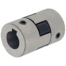
Jaw & Spider Couplings - Set Screw
Click this image to zoom it.
- Volume Discount
You can add up to 6 items per a category to the compare list.
Brand :
Part Number :

Copy Part Number URL to Clipboard
The part number URL has been copied into your clipboard.-
- Order Qty :
-
-
- Price :
- ---
-
- Total Price :
- ---
-
- Days to ship :
- ---
Select part number to Order Now/ Add to Cart
-
- Order Qty. :
-
-
- Price :
- ---
-
- Total Price :
- ---
-
- Days to ship :
- ---
-
- Order Qty. :
-
-
- Price :
- ---
-
- Total Price :
- ---
-
- Days to ship :
- ---
-
- Order Qty. :
-
-
- Price :
- ---
-
- Total Price :
- ---
-
- Days to ship :
- ---
-
- Order Qty. :
-
-
- Price :
- ---
-
- Total Price :
- ---
-
- Days to ship :
- ---
Product Description
New at MISUMI? Get 20% Discount on your First Purchase. Click to Register Now
"Main body and the spider are of smooth blind fit, making for easy installation, removal and maintenance."
Click this image to zoom it.
- Volume Discount
You can add up to 6 items per a category to the compare list.
Brand :
Part Number :
Copy Part Number URL to Clipboard
The part number URL has been copied into your clipboard.-
- Order Qty :
-
-
- Price :
- ---
-
- Total Price :
- ---
-
- Days to ship :
- ---
Select part number to Order Now/ Add to Cart
-
- Order Qty. :
-
-
- Price :
- ---
-
- Total Price :
- ---
-
- Days to ship :
- ---
-
- Order Qty. :
-
-
- Price :
- ---
-
- Total Price :
- ---
-
- Days to ship :
- ---
-
- Order Qty. :
-
-
- Price :
- ---
-
- Total Price :
- ---
-
- Days to ship :
- ---
-
- Order Qty. :
-
-
- Price :
- ---
-
- Total Price :
- ---
-
- Days to ship :
- ---
Dimensional Drawing
| CPJLW With Keywayed Bore d1, d2 | (No. = 50, 70) | (No. = 75, 90, 95) | |||
 |  | ||||
[!] Operating Temperature: -40°C to 100°C
[ ! ] Recommended Fit Tolerance of Applicable Shaft Diameter: h6 and h7.
[ ! ] The lateral, angular, and axial misalignment values shown are for each occurring individually. When multiple misalignments are occurring simultaneously, the allowable maximum value of each will be reduced to 1/2.
| Material | Surface Treatment | |||
| Hub | Spider | Set Screw | Hub | Set Screw |
| Steel Type Sintered Alloy | NBR | SCM435 | Corrosion Resistant Coating | Black Oxide |
Specification Table
| Part Number | — | Shaft Bore Dia. d1 | — | Shaft Bore Dia. d2 |
| CPF20 | — | 10 | — | 10 |
| CPJLW50 | — | 10 | — | 12 |
| Part Number | d1, d2 Selection (However, d1 ≤ d2) | D | L | ℓ | F | Set Screw | ||||||||||||||||||
| Type | No. | M | Tightening Torque (N⋅m) | |||||||||||||||||||||
| CPJLW | 50 | 10 | 11 | 12 | 14 | 15 | 16 | 27.3 | 43.4 | 15.6 | 8 | M6 | 5 | |||||||||||
| 70 | 11 | 12 | 14 | 15 | 16 | 17 | 18 | 19 | 34.4 | 50.2 | 19 | |||||||||||||
| 75 | 14 | 15 | 16 | 17 | 18 | 19 | 20 | 22 | 44.5 | 54.1 | 20.7 | 7 | ||||||||||||
| 90 | 18 | 19 | 20 | 22 | 24 | 25 | 53.6 | 54.6 | 20.7 | 11.2 | ||||||||||||||
| 95 | 18 | 19 | 20 | 22 | 24 | 25 | 28 | 53.6 | 63.8 | 25.3 | M8 | 10 | ||||||||||||
| Part Number | Allowable Torque (N⋅m) | Allowable Angular Misalignment (°) | Allowable Lateral Misalignment (mm) | Static Torsional Spring Constant (N·m/rad) | Max. Rotational Speed (r/min) | Moment of Inertia (kg⋅m2) | Allowable Axial Misalignment (mm) | Mass (g) | |
| Type | No. | ||||||||
| CPJLW | 50 | 2.1 | 1 | 0.38 | 33.4 | 18000 | 1.6 × 10⁻⁵ | +1.0 0 | 90 |
| 70 | 3.6 | 77.7 | 14000 | 3.3 × 10⁻⁵ | 200 | ||||
| 75 | 8.4 | 241 | 11000 | 1.1 × 10⁻⁴ | +1.1 0 | 360 | |||
| 90 | 9.8 | 317 | 9000 | 2.2 × 10⁻⁴ | 520 | ||||
| 95 | 13.1 | 317 | 9000 | 2.6 × 10⁻⁴ | 570 | ||||
■Features
(CPJLW)
○ A flexible coupling with a simple structure by combination of 2 bodies and 1 spider.
○ Main body and the spider are of smooth blind fit. Easy installation, removal and maintenance.
(Body and spider are detachable.)
Part Number
- Incomplete part number.
Please use left hand selections to complete a part number.
Loading...
| Part Number |
|---|
| CPJLW50-12-12 |
| CPJLW50-[10,11,12,14,15,16]-[10,11,12,14,15,16] |
| CPJLW70-[11,12,14,15,16,17,18,19]-[11,12,14,15,16,17,18,19] |
| CPJLW75-[14,15,16,17,18,19,20,22]-[14,15,16,17,18,19,20,22] |
| CPJLW90-[18,19,20,22,24,25]-[18,19,20,22,24,25] |
| CPJLW95-[18,19,20,22,24,25,28]-[18,19,20,22,24,25,28] |
| Part Number | Price | Minimum Order Qty. | Volume Discount | Days to Ship | RoHS | Shaft Bore Dia. 1 d1 (or d) (Ø) | Shaft Bore Dia. 2 d2 (or d) (Ø) | O.D. (Ø) | Overall Length (mm) | Allowable Torque Range (N•m) | Max. Rotational Speed Range (r/min) | Body Material | Allowable Torque (N•m) | Max. Rotational Speed (r/min) | Allowable Axial Misalignment (mm) | Moment of Inertia (kg・m2) | Shaft Bore Dia. 1 (Ø) | Shaft Bore Dia. 2 (Ø) |
|---|---|---|---|---|---|---|---|---|---|---|---|---|---|---|---|---|---|---|
₹ 1,905.00 | 1 Piece(s) | Available | 6 Day(s) or more | - | 12 | 12 | 27.3 | 43.4 | 1.01~3.00 | 10001~78000 | [Steel] Ferrous Sintered Alloy | 2.1 | 18000 | +1.0/0 | 1.6×10⁻⁵ | - | - | |
- | 1 Piece(s) | 8 Day(s) or more | 10 | - | - | 27.3 | 43.4 | 1.01~3.00 | 10001~78000 | [Steel] Steel Type Sintered Alloy | 2.1 | 18000 | +1.0/0 | 1.6 x 10⁻⁵ | 10 ~ 16 | 10 ~ 16 | ||
- | 1 Piece(s) | 8 Day(s) or more | 10 | - | - | 34.4 | 50.2 | 3.01~5.00 | 10001~78000 | [Steel] Steel Type Sintered Alloy | 3.6 | 14000 | +1.0/0 | 3.3 x 10⁻⁵ | 11 ~ 19 | 11 ~ 19 | ||
- | 1 Piece(s) | 8 Day(s) or more | 10 | - | - | 44.5 | 54.1 | 5.01~10.00 | 10001~78000 | [Steel] Steel Type Sintered Alloy | 8.4 | 11000 | +1.1/0 | 1.1 x 10⁻⁴ | 14 ~ 22 | 14 ~ 22 | ||
- | 1 Piece(s) | 8 Day(s) or more | 10 | - | - | 53.6 | 54.6 | 5.01~10.00 | 4001~10000 | [Steel] Steel Type Sintered Alloy | 9.8 | 9000 | +1.1/0 | 2.2 x 10⁻⁴ | 18 ~ 25 | 18 ~ 25 | ||
- | 1 Piece(s) | 8 Day(s) or more | 10 | - | - | 53.6 | 63.8 | 10.01~20.00 | 4001~10000 | [Steel] Steel Type Sintered Alloy | 13.1 | 9000 | +1.1/0 | 2.6 x 10⁻⁴ | 18 ~ 28 | 18 ~ 28 |
| Part Number |
|---|
Loading...
Specifications/Overview
| Keyway Dimension | Shaft bore diameter d1, d2 | b | t | Key Nominal Dim. b × h | |||
 | Standard Dimensions | Tolerance | Standard Dimensions | Tolerance | |||
| 10 | 3 | ±0.0125 | 1.4 | +0.1 0 | 3 × 3 | ||
| 11·12 | 4 | ±0.0150 | 1.8 | 4 × 4 | |||
| 14 to 17 | 5 | 2.3 | 5 × 5 | ||||
| 18 to 22 | 6 | 2.8 | 6 × 6 | ||||
| 24 to 28 | 8 | ±0.0180 | 3.3 | +0.2 0 | 8 × 7 | ||
Basic Information
| Series Name | Jaw & Spider | Application | Standard | Allowable Misalignment | Angular Misalignment / Eccentricity / Axial Misalignment |
|---|---|---|---|---|---|
| Allowable Angular Misalignment(deg) | 1 | Allowable Lateral Misalignment(mm) | 0.38 | Product Category | Coupling Main Body |
| Allowable Lateral Misalignment Range(mm) | 0.21~0.40 | Operating Temperature(°C) | -40::100 |
- The specifications and dimensions of some parts may not be fully covered. For exact details, refer to manufacturer catalogs .
Payment Method
- Credit Card
-
- Debit Cart
-
- Net Banking
-
- UPI
-
- Cheque on delivery
-
- Online payment
-
Social Media
MISUMI India Contact
Copyright © MISUMI Corporation All Rights Reserved.
- Not a MISUMI customer yet?
- Register and enjoy 20% Off
- on your 1st order! *
- Download CAD data and product data for more than 12 Mio. products.
- Configure your drawing parts in the MISUMI Online Shop and save time and resources.
- Reduce your process costs with the MISUMI Online Shop.


How can we improve?
How can we improve?
Thank you for your time.
Your feedback is essential for our continuous improvement
Privacy Policy
Thank you for your cooperation.
Thank you for your time.
Your feedback is essential for our continuous improvement
Please use the inquiry form.
Privacy Policy