The Critical Role of Couplings in Power Transmission
Publish Date: 06 November 2025
Every high-performance machine relies on a fundamental connection to transfer energy from the engine to the work—and that connection is the coupling. In the world of industrial machinery, the coupling is an indispensable component, serving as the crucial link that ensures power flows smoothly and safely.
What Exactly is a Coupling?
A shaft coupling (or sometimes referred to by its structure, like a sprocket coupling) is a mechanical device used to connect the power transmission system between the energy source and the component that does the work.
- Driver: The input side, typically a motor.
- Driven: The output side, such as a shaft or a ball screw.
The coupling bridges this gap, creating a seamless mechanical pathway.
Why Can't We Just Bolt the Shafts Together? The Function of a Coupling
You might think, "Why not just use a rigid connector?" The simple answer is that in a real-world, dynamic machine, perfect alignment is impossible to maintain. Even if two shafts are perfectly aligned when stationary, factors immediately introduce misalignments and stress when the machine starts running:
- 1. Shaft Deflection: The ball screw or driven shaft will naturally bend or flex under operational loads.
- 2. Thermal Expansion: As the machine heats up, components change shape, creating misalignment.
- 3. Clamping Changes: Changes in the shape of support devices (like load support devices) can shift the shaft's position.
- 4. Wear and Tear: Over time, friction and use cause the bearings to wear, introducing eccentricity (off-center rotation).
If the connection were rigid, these forces would lead to immediate failure, excessive vibration, and damage to the motor and driven components. Therefore, we use flexible shaft couplings—their job is to absorb these stresses and misalignments, ensuring the machine operates smoothly and reducing damage caused by these inevitable operational changes.
Deep Dive: Properties and Structure of Key Coupling Types
Flexible couplings achieve their goal through different clever designs, each suited for a specific application:
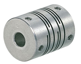
1. Slit Coupling
The Slit Coupling is an excellent example of compact engineering.
- Structure: This is a one-piece cylindrical metal body (often aluminum alloy) featuring a spiral slit cut into it. This slit gives the single piece of material a spring-like flexibility.
- Features: Its one-piece structure ensures it transmits torque smoothly and excels at compensating for eccentricity (parallel misalignment) between shafts. It provides good power transmission in the backlash phase (when motion reverses) and is highly resistant to water, oil, and chemicals.
2. Disc Coupling
The Disc Coupling is known for its versatility and high performance.
- Structure: It connects the two shaft hubs using a thin, flexible disc (or series of discs) in the middle. The material and shape of this disc are key to its power transmission capabilities.
- Features: Its one-piece structure ensures it transmits torque smoothly and excels at compensating for eccentricity Highly versatile, the Disc Coupling is resistant to twisting (torsion) and can handle high torque. Like the Slit Coupling, it provides robust power transmission during the backlash period.
3. Oldham’s Coupling
The Oldham's Coupling is designed to handle significant parallel misalignment in a compact package.
- Structure: It uses two outer axle hubs connected by a central, typically plastic, spacer. The hubs fit into perpendicular slots in the spacer, allowing for relative sliding motion.
- Features: It is compact and designed for low-torque applications. It resists torsion, maintains balance during power transmission, and is highly effective at compensating for misalignment (both parallel and angular).
4. Bellows Coupling
The Bellows Coupling is engineered for precision and speed, making it the choice for feedback systems.
- Structure: It features a distinctive bellows shape (like a snake's belly or accordion) made from materials like phosphor bronze or stainless steel, which connects the two shaft hubs.
- Features: Due to its excellent torsional stiffness and low inertia, it is highly suitable for use with Encoders—devices that require extremely accurate and high-speed power transmission to measure position and speed without any slack.
Understanding these specialized designs ensures you select the perfect coupling to maximize your machinery's lifespan and output.
The Final Piece: Maintaining and Troubleshooting Couplings
Once you've selected and installed the perfect coupling, its ongoing care is vital. Proper maintenance extends the lifespan of the coupling and, more importantly, protects the expensive motor and driven equipment from damage.
Monitoring and Maintenance
Couplings are generally durable, but they are subject to constant stress. Regular checks are essential:
- Vibration and Noise Checks: A properly functioning coupling runs smoothly and quietly. An increase in vibration or the appearance of unusual sounds (clattering, scraping, or knocking) almost always signals a problem—likely excessive misalignment or component wear.
- Visual Inspection: Regularly inspect the coupling for visible damage. Look for cracks on metal components, perishing or softening of flexible elements (like plastic spacers or bellows), or signs of fretting (wear) due to excessive movement.
- Re-Alignment Checks: Over time, the machinery base or frame may shift due to settling, temperature changes, or mechanical stress. Periodically verify the alignment of the connected shafts to ensure the coupling is not being forced beyond its intended compensation limits.
Common Coupling Issues and Solutions
Troubleshooting is often about identifying the symptom and tracing it back to the root cause:
| Symptom | Probable Cause | Corrective Action |
|---|---|---|
| Excessive Vibration/Noise | Significant misalignment (angular or parallel) or a worn/damaged flexible element. | Stop operation, re-align the shafts precisely, and replace any worn components (spacer, disc, etc.). |
| Heat Generation at Coupling | Severe misalignment or the coupling's torque capacity is undersized for the load. | Check alignment. If alignment is correct, consider upgrading to a coupling with a higher torque rating (e.g., from an Oldham's to a Disc type). |
| Premature Failure of Flexible Element | Consistent over-torque or repeated high loads. | Review the application's maximum torque requirement and ensure the coupling's rating is appropriate. Check for sudden starts/stops. |
| Bolts/Keys Loosening | High cyclic torque loads or improper installation torque. | Re-torque all fasteners to manufacturer specifications. Use thread-locking compounds if necessary. |
Conclusion:
The coupling is often an unseen regulator in any mechanical system. It doesn't generate power, but it dictates how that power is delivered. By selecting the correct type—whether a flexible Slit Coupling for compact tolerance or a robust Disc Coupling for high torque—and following a strict maintenance regime, you ensure the longevity and efficiency of your entire drivetrain.


