(!)NOTE : Windows 7 users won’t be able to use some latest features of eCatalog/WOS since Microsoft is ending support for Windows 7 on 14 Jan, 2020. Please upgrade your system for uninterrupted services.
- Due to an increase in demand, the lead time of some of the electrical items from our eCatalogue has increased abnormally and may cause delays in delivery or order suspension. We apologize for the inconvenience and appreciate your kind understanding. Once the supply will get normalized, we will update the same.
-
 My Components
-
 Similar Products
 Product Detail
- CAD Data unavailable
轴孔经(加工完毕)d1
轴孔经(加工完毕)d2
外径D
全长L
Allowable Torque
Allowable Lateral Misalignment
Max. Rotational Speed
type
Days to Ship
Specification/Dimensions
-
轴孔经(加工完毕)d1(Ø)
-
轴孔经(加工完毕)d2(Ø)
-
外径D(Ø)
-
全长L(mm)
-
Allowable Torque(N•m)
-
Allowable Lateral Misalignment(mm)
-
Max. Rotational Speed(r/min)
-
type
- E-LMCPS
Days to Ship
-
- All
- 9 Day(s) or Less
Specify Alterations
Single Disc Couplings Clamping Type

You can add up to 6 items per a category to the compare list.
Brand :
MiSUMi Economy
Part Number :

Copy Part Number URL to Clipboard
The part number URL has been copied into your clipboard.-
- Order Qty :
-
-
- Price :
- ---
-
- Total Price :
- ---
-
- Days to ship :
- ---
Select part number to Order Now/ Add to Cart
- CAD Data unavailable
Product Description
This is an economy item, The price is cheaper than the MISUMI standard product.
Product Overview
Disc coupling is made of several sets of discs (stainless steel sheet) bolted staggered with two coupling halves, each set of discs by several pieces of stacked set.
The disc coupling relies on the elastic deformation of the disc to compensate for the relative displacement of the two shafts connected, is a high-performance flexible coupling with strong metal components.
It is characterized by compact structure, zero backlash, high strength, long service life, no rotating clearance, unaffected by temperature and oil, acid and alkali resistant and corrosion resistant.
Applicable motor types: Recommended for servo motors, stepper motors and general motors.
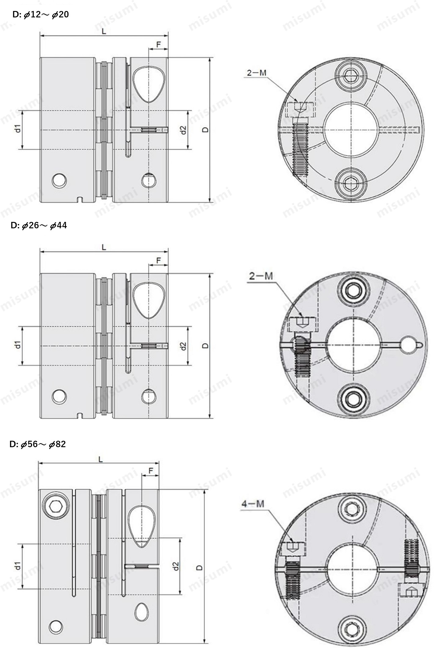
Dimensional Drawing
Clamping Type
Material table

Material table
| Type | Part |  Material Material |  Surface Treatment Surface Treatment |  Accessory Accessory |
| E-LMCPS | Hub | Aluminum Alloy | Clear Anodize | Hex Socket Clamp Screw |
| Disk | Stainless Steel | - |
Specification Table
Please follow the selection steps ~
~ to select the part no. Please specify the shaft hole diameter within the range of d1≤d2.

 ~
~ to select the part no. Please specify the shaft hole diameter within the range of d1≤d2.
Part No.(Type· D) D) | - |  d1 d1 | - | d2 |
| E-LMCPS12 | - | 3 | - | 5 |
| E-LMCPS20 | - | 4 | - | 6 |
| Part No. | d1、d2Shaft Hole Dia.(d1≤d2) | L | ||||||||||||||||||||||||||||||
| Type | D | |||||||||||||||||||||||||||||||
| E-LMCPS | 12 | 3 | 4 | 5 | 12.35 | |||||||||||||||||||||||||||
| 16 | 3 | 4 | 5 | 6 | 17 | |||||||||||||||||||||||||||
| 19 | 3 | 4 | 5 | 6 | 6.35 | 7 | 8 | 20 | ||||||||||||||||||||||||
| 20 | 3 | 4 | 5 | 6 | 6.35 | 7 | 8 | 23 | ||||||||||||||||||||||||
| 26 | 3 | 4 | 5 | 6 | 6.35 | 7 | 8 | 9 | 9.525 | 10 | 11 | 12 | 14 | 26 | ||||||||||||||||||
| 29 | 5 | 6 | 6.35 | 7 | 8 | 9 | 9.525 | 10 | 11 | 12 | 25.7 | |||||||||||||||||||||
| 32 | 5 | 6 | 6.35 | 7 | 8 | 9 | 9.525 | 10 | 11 | 12 | 12.7 | 14 | 15 | 28 | ||||||||||||||||||
| 33 | 5 | 6 | 6.35 | 7 | 8 | 9 | 9.525 | 10 | 11 | 12 | 12.7 | 14 | 15 | 28.5 | ||||||||||||||||||
| 34 | 5 | 6 | 6.35 | 8 | 9 | 9.525 | 10 | 11 | 12 | 12.7 | 14 | 15 | 16 | 32 | ||||||||||||||||||
| 39 | 8 | 9 | 9.525 | 10 | 11 | 12 | 12.7 | 14 | 15 | 16 | 17 | 18 | 19 | 34.5 | ||||||||||||||||||
| 44 | 8 | 9 | 9.525 | 10 | 11 | 12 | 12.7 | 14 | 15 | 16 | 17 | 18 | 19 | 20 | 22 | 24 | 34.5 | |||||||||||||||
| 56 | 10 | 12 | 14 | 15 | 16 | 17 | 18 | 19 | 20 | 22 | 24 | 25 | 28 | 30 | 32 | 45 | ||||||||||||||||
| 68 | 12 | 14 | 15 | 16 | 17 | 18 | 19 | 20 | 22 | 24 | 25 | 28 | 30 | 32 | 35 | 38 | 53 | |||||||||||||||
| 82 | 17 | 18 | 19 | 20 | 22 | 24 | 25 | 28 | 30 | 32 | 35 | 38 | 40 | 42 | 68 | |||||||||||||||||
| Part No. | L | F | Clamp Screw | Rated Torque (N·m) | Mass (g) | ||
| Type | D | M | Tightening torque N.m | ||||
| E-LMCPS | 12 | 12.35 | 2.2 | M1.6 | 0.23~0.28 | 0.25 | 3 |
| 16 | 17 | 2.6 | M2 | 0.4~0.5 | 0.6 | 7 | |
| 19 | 20 | 3.2 | M2.5 | 1 | 1 | 11 | |
| 20 | 23 | 3.2 | M2.5 | 1 | 1 | 20 | |
| 26 | 26 | 4 | M3 | 1.5 | 2 | 28 | |
| 29 | 25.7 | 4 | M3 | 1.5 | 2 | 35 | |
| 32 | 28 | 4 | M3 | 1.5 | 6 | 46 | |
| 33 | 28.5 | 4 | M3 | 1.5 | 6 | 50 | |
| 34 | 32 | 5 | M4 | 3.5 | 6 | 55 | |
| 39 | 34.5 | 5.2 | M4 | 3.5 | 13 | 81 | |
| 44 | 34.5 | 5.2 | M4 | 3.5 | 15 | 99 | |
| 56 | 45 | 6.3 | M5 | 8 | 25 | 217 | |
| 68 | 53 | 7.7 | M6 | 13 | 60 | 348 | |
| 82 | 68 | 9.8 | M8 | 28 | 80 | 689 | |
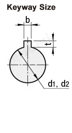
Alterations


| Shaft Hole Dia. d1 · d2 | b(Keyway Width) | t Keyway Depth | Keyway Nominal Dim. b X h | |
| LK | RK | |||
| 6 ~ 7.9 | 2 | 2 | 1 | 2x2 |
| 8~10 | 3 | 3 | 1.4 | 3x3 |
| 11~12 | 4 | 4 | 1.8 | 4x4 |
| 13~17 | 5 | 5 | 2.3 | 5x5 |
| 18~22 | 6 | 6 | 2.8 | 6x6 |
| 23~30 | 8 | 8 | 3.3 | 8x7 |
| 31~38 | 10 | 10 | 3.3 | 10x8 |
| 39~44 | 12 | 12 | 3.3 | 12x8 |
Product Features
■Main characteristics of Disc Couplings
1. Strong capability to compensate for misalignment of two shafts, offering twice the angular displacement compared to Jaw couplings, lower reactionary forces during radial displacement, high flexibility, and allows for certain axial, radial, and angular displacements.
2. Provides significant vibration damping effects, operates without noise, and wear-free.
3. Can safely operate under conditions of shock and vibration.
4. High transmission efficiency, up to 99.86%, particularly suitable for medium and high-speed, high-power transmission.
5. Simple structure, lightweight, small volume, and convenient for assembly and disassembly. Installation and removal can be done without moving the machine (refers to the type with an intermediate shaft) and does not require lubrication.
6. Can accurately transmit rotational speed, operates without slip, suitable for the transmission of precision machinery.
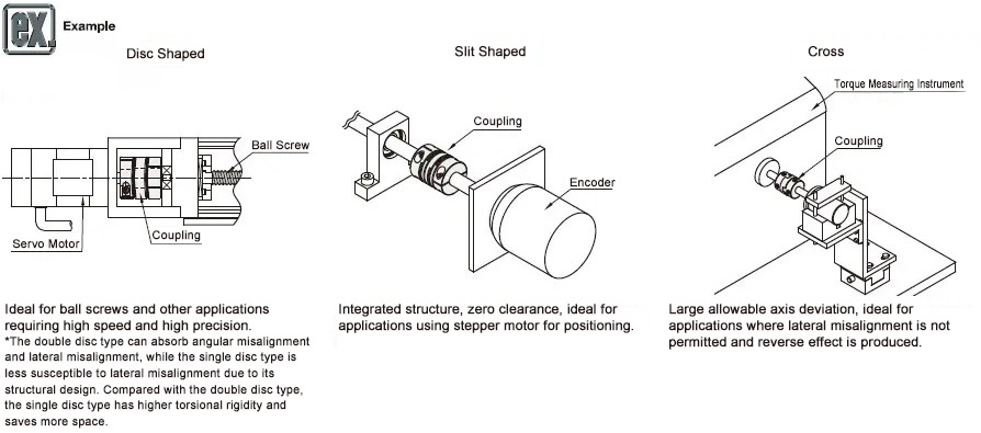
Example of Use

Precautions
■Calibration adjustment
1. The coupling allows shaft center deviation and transmits rotation angle and torque. However, when the shaft center deviation exceeds the allowable value, vibration will occur or the service life will be drastically reduced.
2. Axis deviation includes eccentricity (parallel error of two axes), declination (angular error of two axes), and axial amplitude (axial movement of the shaft).
Please calibrate and adjust the shaft to ensure that the axis center deviation is below the allowable value stated in the dimensions and performance table of each product.
3. The allowable value of axial misalignment stated in the dimensions and performance table refers to the situation when one of eccentricity, declination, or axial amplitude occurs alone.
When more than two axis deviations occur at the same time, the corresponding allowable values will be halved respectively.
4. Axial misalignment not only occurs when assembling to the device, but also occurs due to vibration, thermal expansion, bearing wear, etc. during operation. Therefore, it is recommended to set the axis deviation to less than 1/3 of the allowable value.
| Part Number |
|---|
| E-LMCPS12-[3,4,5]-[3,4,5] |
| E-LMCPS16-[3,4,5,6]-[3,4,5,6] |
| E-LMCPS19-[3,4,5,6,6.35,7,8]-[3,4,5,6,6.35,7,8] |
| E-LMCPS20-[3,4,5,6,6.35,7,8]-[3,4,5,6,6.35,7,8] |
| E-LMCPS26-[3,4,5,6,6.35,7,8,9,9.525,10,11,12,13,14]-[3,4,5,6,6.35,7,8,9,9.525,10,11,12,13,14] |
| E-LMCPS29-[5,6,6.35,7,8,9,9.525,10,11,12,14]-[5,6,6.35,7,8,9,9.525,10,11,12,14] |
| E-LMCPS32-[5,6,6.35,7,8,9,9.525,10,11,12,12.7,14,15]-[5,6,6.35,7,8,9,9.525,10,11,12,12.7,14,15] |
| E-LMCPS33-[5,6,6.35,7,8,9,9.525,10,11,12,12.7,13,14,15]-[5,6,6.35,7,8,9,9.525,10,11,12,12.7,13,14,15] |
| E-LMCPS34-[5,6,6.35,7,8,9,9.525,10,11,12,12.7,13,14,15,16]-[5,6,6.35,7,8,9,9.525,10,11,12,12.7,13,14,15,16] |
| E-LMCPS39-[8,9,9.525,10,11,12,12.7,14,15,16,17,18,19]-[8,9,9.525,10,11,12,12.7,14,15,16,17,18,19] |
| E-LMCPS44-[8,9,9.525,10,11,12,12.7,14,15,16,17,18,19,20,22,24]-[8,9,9.525,10,11,12,12.7,14,15,16,17,18,19,20,22,24] |
| E-LMCPS56-[10,12,14,15,16,17,18,19,20,22,24,25,28,30,32]-[10,12,14,15,16,17,18,19,20,22,24,25,28,30,32] |
| E-LMCPS68-[12,14,15,16,17,18,19,20,22,24,25,28,30,32,35,38]-[12,14,15,16,17,18,19,20,22,24,25,28,30,32,35,38] |
| E-LMCPS82-[17,18,19,20,22,24,25,28,30,32,35,38,40,42]-[17,18,19,20,22,24,25,28,30,32,35,38,40,42] |
| Part Number | Price | Minimum Order Qty. | Volume Discount | Days to Ship | 轴孔经(加工完毕)d1 (Ø) | 轴孔经(加工完毕)d2 (Ø) | 外径D (Ø) | 全长L (mm) | Allowable Torque (N•m) | Allowable Lateral Misalignment (mm) | Max. Rotational Speed (r/min) | Allowable Axial Misalignment (mm) | Moment of Inertia (kg・m2) |
|---|---|---|---|---|---|---|---|---|---|---|---|---|---|
- | 1 Piece(s) | 9 Day(s) | 3 ~ 5 | 3 ~ 5 | 12 | 12.35 | 0.25 | 0.01 | 10000 | ±0.08 | 5.9×10⁻⁸ | ||
- | 1 Piece(s) | 9 Day(s) | 3 ~ 6 | 3 ~ 6 | 16 | 17 | 0.6 | 0.02 | 10000 | ±0.1 | 2.63×10⁻⁷ | ||
- | 1 Piece(s) | 9 Day(s) | 3 ~ 8 | 3 ~ 8 | 19 | 20 | 1 | 0.1 | 10000 | ±0.18 | 6.7×10⁻⁷ | ||
- | 1 Piece(s) | 9 Day(s) | 3 ~ 8 | 3 ~ 8 | 20 | 23 | 1 | 0.1 | 10000 | ±0.20 | 2.2×10⁻⁶ | ||
- | 1 Piece(s) | 9 Day(s) | 3 ~ 14 | 3 ~ 14 | 26 | 26 | 2 | 0.1 | 10000 | ±0.30 | 2.2×10⁻⁶ | ||
- | 1 Piece(s) | 9 Day(s) | 5 ~ 14 | 5 ~ 14 | 29 | 25.7 | 2 | 0.1 | 10000 | ±0.30 | 6.7×10⁻⁶ | ||
- | 1 Piece(s) | 9 Day(s) | 5 ~ 15 | 5 ~ 15 | 32 | 28 | 6 | 0.1 | 10000 | ±0.36 | 7.1×10⁻⁶ | ||
- | 1 Piece(s) | 9 Day(s) | 5 ~ 15 | 5 ~ 15 | 33 | 28.5 | 6 | 0.1 | 10000 | ±0.40 | 7.8×10⁻⁶ | ||
- | 1 Piece(s) | 9 Day(s) | 5 ~ 16 | 5 ~ 16 | 34 | 32 | 6 | 0.1 | 10000 | ±0.36 | 8.0×10⁻⁶ | ||
- | 1 Piece(s) | 9 Day(s) | 8 ~ 19 | 8 ~ 19 | 39 | 34.5 | 13 | 0.1 | 10000 | ±0.45 | 2.2×10⁻⁵ | ||
- | 1 Piece(s) | 9 Day(s) | 8 ~ 24 | 8 ~ 24 | 44 | 34.5 | 15 | 0.1 | 10000 | ±0.54 | 2.8×10⁻⁵ | ||
- | 1 Piece(s) | 9 Day(s) | 10 ~ 32 | 10 ~ 32 | 56 | 45 | 28 | 0.1 | 10000 | ±0.72 | 1.2×10⁻⁴ | ||
- | 1 Piece(s) | 9 Day(s) | 12 ~ 38 | 12 ~ 38 | 68 | 53 | 60 | 0.1 | 9000 | ±0.80 | 1.5×10⁻⁴ | ||
- | 1 Piece(s) | 9 Day(s) | 17 ~ 42 | 17 ~ 42 | 82 | 68 | 100 | 0.1 | 8000 | ±0.80 | 1.8×10⁻⁴ |
Loading...
Basic Information
| Series Name | Disc | Application | For Servo Motors / Stepping Motor | Features | High Torsional Rigidity / High Torque Type |
|---|---|---|---|---|---|
| Allowable Misalignment | Angular Misalignment / Eccentricity / Axial Misalignment | Body Material | Aluminum Alloy | Product Category | Coupling Main Body |
| Disc Material | Stainless Steel | Single/Double | Single Disc | Shaft Tightening Method | Fastening Bolt |
| Shaft Hole Shape | Standard |
- The specifications and dimensions of some parts may not be fully covered. For exact details, refer to manufacturer catalogs .
Frequently asked question (FAQ)
- Question: What is a coupling?
- Answer: A coupling is a part that connects two different rotating bodies (motor shaft, ball screw, etc.) and aims at transmitting torque. The load of assembly adjustment is reduced by absorbing the axis deviation (lateral misalignment, angular misalignment and axial amplitude) between rotating bodies. And in case of accidental overload, the coupling is destroyed and the rotating bodies are disconnected to protect the expensive power part and the whole device.
- Question: Which disc type coupling is better, single disc type or double disc type?
-
Answer:
Double disc type can absorb angular misalignment and lateral misalignment, but the total length will increase.
Although the total length of the single disc type is short, it is only suitable for applications with narrow space because lateral misalignment is not allowed in the structure.
Special attention should be paid to centering during use. - Question: Abnormal sound or vibration occurs during use of disc type coupling.
-
Answer:
When a servo motor is used, the frequency of the mechanical resonance suppression filter is set as its inherent vibration frequency in the control system to suppress sound and vibration.
When using a stepping motor, the rotational speed can be finely adjusted, or the vibration can be absorbed and suppressed by the high damping rubber type coupling with obvious attenuation effect. - Question: How to achieve the effect of applicable lateral misalignment and angular misalignment in product design?
- Answer: The plate spring formed by the slit allows lateral misalignment, angular misalignment and end play.
- Question: What does the product need for applications of lateral misalignment and angular misalignment?
- Answer: Lateral misalignment, angular misalignment and axial amplitude are all single allowable values. If there are multiple deviations at the same time, the allowable value of each deviation will be reduced to 1/2 of the original value.
Payment Method
- Credit Card
-
- Debit Cart
-
- Net Banking
-
- UPI
-
- Cheque on delivery
-
- Online payment
-
Social Media
MISUMI India Contact
Copyright © MISUMI Corporation All Rights Reserved.
How can we improve?
How can we improve?
Thank you for your time.
Your feedback is essential for our continuous improvement
Privacy Policy
Thank you for your cooperation.
Thank you for your time.
Your feedback is essential for our continuous improvement
Please use the inquiry form.
Privacy Policy